
5.2C: Step-by-Step Procedures
- Page ID
- 95715

\( \newcommand{\vecs}[1]{\overset { \scriptstyle \rightharpoonup} {\mathbf{#1}} } \)
\( \newcommand{\vecd}[1]{\overset{-\!-\!\rightharpoonup}{\vphantom{a}\smash {#1}}} \)
\( \newcommand{\dsum}{\displaystyle\sum\limits} \)
\( \newcommand{\dint}{\displaystyle\int\limits} \)
\( \newcommand{\dlim}{\displaystyle\lim\limits} \)
\( \newcommand{\id}{\mathrm{id}}\) \( \newcommand{\Span}{\mathrm{span}}\)
( \newcommand{\kernel}{\mathrm{null}\,}\) \( \newcommand{\range}{\mathrm{range}\,}\)
\( \newcommand{\RealPart}{\mathrm{Re}}\) \( \newcommand{\ImaginaryPart}{\mathrm{Im}}\)
\( \newcommand{\Argument}{\mathrm{Arg}}\) \( \newcommand{\norm}[1]{\| #1 \|}\)
\( \newcommand{\inner}[2]{\langle #1, #2 \rangle}\)
\( \newcommand{\Span}{\mathrm{span}}\)
\( \newcommand{\id}{\mathrm{id}}\)
\( \newcommand{\Span}{\mathrm{span}}\)
\( \newcommand{\kernel}{\mathrm{null}\,}\)
\( \newcommand{\range}{\mathrm{range}\,}\)
\( \newcommand{\RealPart}{\mathrm{Re}}\)
\( \newcommand{\ImaginaryPart}{\mathrm{Im}}\)
\( \newcommand{\Argument}{\mathrm{Arg}}\)
\( \newcommand{\norm}[1]{\| #1 \|}\)
\( \newcommand{\inner}[2]{\langle #1, #2 \rangle}\)
\( \newcommand{\Span}{\mathrm{span}}\) \( \newcommand{\AA}{\unicode[.8,0]{x212B}}\)
\( \newcommand{\vectorA}[1]{\vec{#1}} % arrow\)
\( \newcommand{\vectorAt}[1]{\vec{\text{#1}}} % arrow\)
\( \newcommand{\vectorB}[1]{\overset { \scriptstyle \rightharpoonup} {\mathbf{#1}} } \)
\( \newcommand{\vectorC}[1]{\textbf{#1}} \)
\( \newcommand{\vectorD}[1]{\overrightarrow{#1}} \)
\( \newcommand{\vectorDt}[1]{\overrightarrow{\text{#1}}} \)
\( \newcommand{\vectE}[1]{\overset{-\!-\!\rightharpoonup}{\vphantom{a}\smash{\mathbf {#1}}}} \)
\( \newcommand{\vecs}[1]{\overset { \scriptstyle \rightharpoonup} {\mathbf{#1}} } \)
\(\newcommand{\longvect}{\overrightarrow}\)
\( \newcommand{\vecd}[1]{\overset{-\!-\!\rightharpoonup}{\vphantom{a}\smash {#1}}} \)
\(\newcommand{\avec}{\mathbf a}\) \(\newcommand{\bvec}{\mathbf b}\) \(\newcommand{\cvec}{\mathbf c}\) \(\newcommand{\dvec}{\mathbf d}\) \(\newcommand{\dtil}{\widetilde{\mathbf d}}\) \(\newcommand{\evec}{\mathbf e}\) \(\newcommand{\fvec}{\mathbf f}\) \(\newcommand{\nvec}{\mathbf n}\) \(\newcommand{\pvec}{\mathbf p}\) \(\newcommand{\qvec}{\mathbf q}\) \(\newcommand{\svec}{\mathbf s}\) \(\newcommand{\tvec}{\mathbf t}\) \(\newcommand{\uvec}{\mathbf u}\) \(\newcommand{\vvec}{\mathbf v}\) \(\newcommand{\wvec}{\mathbf w}\) \(\newcommand{\xvec}{\mathbf x}\) \(\newcommand{\yvec}{\mathbf y}\) \(\newcommand{\zvec}{\mathbf z}\) \(\newcommand{\rvec}{\mathbf r}\) \(\newcommand{\mvec}{\mathbf m}\) \(\newcommand{\zerovec}{\mathbf 0}\) \(\newcommand{\onevec}{\mathbf 1}\) \(\newcommand{\real}{\mathbb R}\) \(\newcommand{\twovec}[2]{\left[\begin{array}{r}#1 \\ #2 \end{array}\right]}\) \(\newcommand{\ctwovec}[2]{\left[\begin{array}{c}#1 \\ #2 \end{array}\right]}\) \(\newcommand{\threevec}[3]{\left[\begin{array}{r}#1 \\ #2 \\ #3 \end{array}\right]}\) \(\newcommand{\cthreevec}[3]{\left[\begin{array}{c}#1 \\ #2 \\ #3 \end{array}\right]}\) \(\newcommand{\fourvec}[4]{\left[\begin{array}{r}#1 \\ #2 \\ #3 \\ #4 \end{array}\right]}\) \(\newcommand{\cfourvec}[4]{\left[\begin{array}{c}#1 \\ #2 \\ #3 \\ #4 \end{array}\right]}\) \(\newcommand{\fivevec}[5]{\left[\begin{array}{r}#1 \\ #2 \\ #3 \\ #4 \\ #5 \\ \end{array}\right]}\) \(\newcommand{\cfivevec}[5]{\left[\begin{array}{c}#1 \\ #2 \\ #3 \\ #4 \\ #5 \\ \end{array}\right]}\) \(\newcommand{\mattwo}[4]{\left[\begin{array}{rr}#1 \amp #2 \\ #3 \amp #4 \\ \end{array}\right]}\) \(\newcommand{\laspan}[1]{\text{Span}\{#1\}}\) \(\newcommand{\bcal}{\cal B}\) \(\newcommand{\ccal}{\cal C}\) \(\newcommand{\scal}{\cal S}\) \(\newcommand{\wcal}{\cal W}\) \(\newcommand{\ecal}{\cal E}\) \(\newcommand{\coords}[2]{\left\{#1\right\}_{#2}}\) \(\newcommand{\gray}[1]{\color{gray}{#1}}\) \(\newcommand{\lgray}[1]{\color{lightgray}{#1}}\) \(\newcommand{\rank}{\operatorname{rank}}\) \(\newcommand{\row}{\text{Row}}\) \(\newcommand{\col}{\text{Col}}\) \(\renewcommand{\row}{\text{Row}}\) \(\newcommand{\nul}{\text{Nul}}\) \(\newcommand{\var}{\text{Var}}\) \(\newcommand{\corr}{\text{corr}}\) \(\newcommand{\len}[1]{\left|#1\right|}\) \(\newcommand{\bbar}{\overline{\bvec}}\) \(\newcommand{\bhat}{\widehat{\bvec}}\) \(\newcommand{\bperp}{\bvec^\perp}\) \(\newcommand{\xhat}{\widehat{\xvec}}\) \(\newcommand{\vhat}{\widehat{\vvec}}\) \(\newcommand{\uhat}{\widehat{\uvec}}\) \(\newcommand{\what}{\widehat{\wvec}}\) \(\newcommand{\Sighat}{\widehat{\Sigma}}\) \(\newcommand{\lt}{<}\) \(\newcommand{\gt}{>}\) \(\newcommand{\amp}{&}\) \(\definecolor{fillinmathshade}{gray}{0.9}\)Condenser Hoses
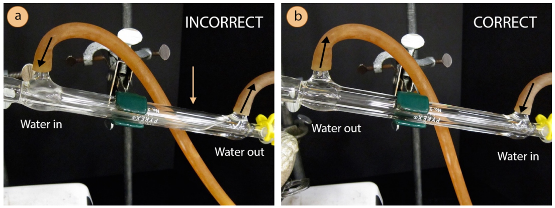
The condenser is an intricate piece of glassware, and allows for cold water to circulate through the distillation apparatus. The circulating water does not mix with the sample to be purified, but instead passes through another jacket surrounding the hollow tube where the gaseous sample travels. It is important that the water jacket be full of cold water, to maximize the efficiency of condensing the gaseous sample. It is for this reason that the water hoses must be attached to the condenser in a certain way.
A hose should connect from the water spigot to the lower arm of the condenser, forcing water to travel against gravity through the condenser (this is shown correctly in Figure 5.17b). The hose connecting the upper arm of the condenser should then drain to the sink. By forcing the water uphill, it will completely fill the condenser. The hoses are connected incorrectly in Figure 5.17a, with water flowing into the upper arm of the condenser. With a downhill flow of water, only the lower portion of the condenser fills with the circulating water, leading to inefficient cooling of gas traveling through the inner tube.
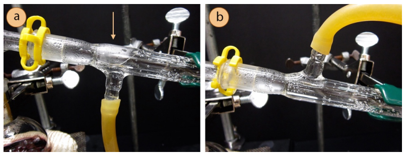
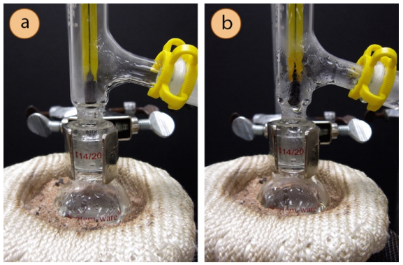
Whether the condenser hoses point up or down seems to be a personal choice, as there are pros and cons to both orientations. When the hoses point downward, there is a small portion of the condenser that does not fill with cooling water (Figure 5.18a), but the effect is likely minimal. When the hoses point upwards, there is sometimes a tendency for the hoses to bend and pop off, spraying water all over the lab (this can sometimes be avoided by securing wire around the hose joints). Personal judgment may be applied to whether the condenser hoses point up or down.
Simple Distillation Procedure
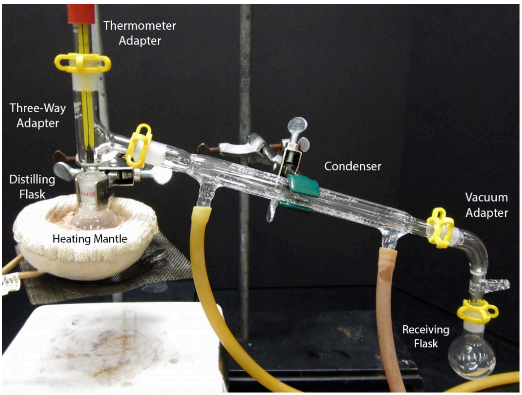
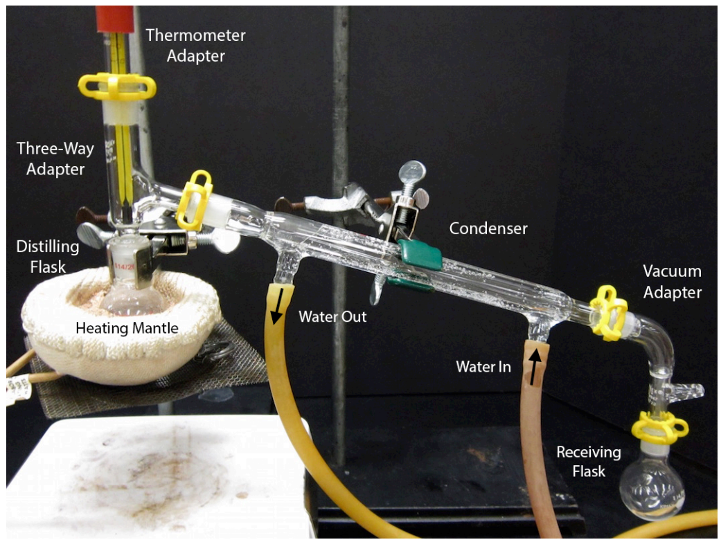
An assembled simple distillation apparatus is shown in Figure 5.19. Assembly of this complicated apparatus is shown in this section piece by piece. The glassware used for this apparatus is quite expensive, and undoubtedly your instructor would appreciate care being taken when using this experiment. A single condenser costs $72, and a complete kit containing all the glassware needed for distillation costs $550!\(^8\)
Assemble the Apparatus:
- To visualize the assembly of the apparatus, it may be helpful to first lay out the glassware on the benchtop before assembling the parts (Figure 5.21a).
- Pour the liquid to be distilled into a round bottomed flask, trying to avoid pouring liquid on the ground glass joint. If liquid drops onto the joint, wipe it off with a KimWipe. Alternatively use a funnel to be sure no liquid ends up on the joint, which can sometimes cause the joint to freeze.
The flask should ideally be between one-third to one-half full of the liquid to be distilled. If the flask is more than half full, it will be difficult to control the boil. If less than a third full, the recovery may be compromised, as there is a quantity of vapor required to fill the flask that will not distill over (this is called the "holdup volume", and later condenses when the flask is cooled). - Add a few boiling stones or magnetic stir bar to the solution to prevent bumping during heating.
- Use a metal extension clamp to secure the round bottomed flask containing the sample to the ring stand or latticework at least 4 inches above the benchtop (to leave room for the heat source). The clamp should securely hold the joint below the glass protrusion on the flask (Figure 5.21b, not FIgure 5.21c).
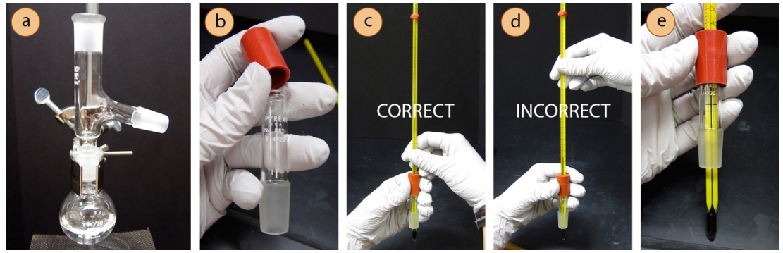
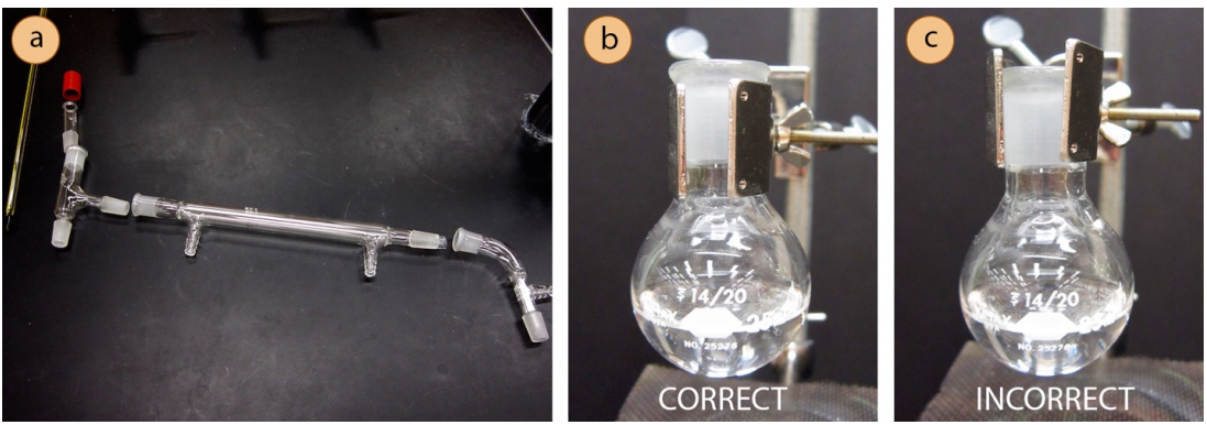
- Attach a three-way adapter (or "distilling adapter") to the round bottomed flask (Figure 5.22a). [If using grease as recommended by your instructor, lightly grease all joints.]
- Attach a rubber fitting to the top of a thermometer adapter (a cylindrical tube, Figure 5.22b) by stretching it over the glass. Then delicately insert a thermometer into the hole of the rubber fitting.
Safety note: While inserting the thermometer, position your hands near the joint (Figure 5.22c), not far from the joint or it may snap (Figure 5.22d). A prepared thermometer adapter with inserted thermometer is shown in Figure 5.22e.
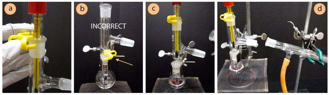
- Connect the thermometer adapter to the three-way adapter, securing the joint with a plastic clip (sometimes called a "Keck clip", the yellow clip in Figure 5.23a). The clip is directional, and if it doesn't easily snap on it is probably upside down. Check that the clip is not broken, and if it is, replace it.
A plastic clip should not be used to connect the round bottomed flask to the three-way adapter (Figure 5.23b) for two reasons. First, this is one of the hottest parts of the apparatus, and could cause the plastic to melt (especially if the compound has a high boiling point or a strong heat source is used). Secondly, a plastic clip in this location interferes with a secure grip by the metal extension clamp. A secure clamp on the flask is necessary in order to maintain the integrity of the system while lowering the heat source at the end of the distillation. - Adjust the thermometer so the bulb is just below the arm of the adapter (Figure 5.23c). If the bulb is positioned too high, it will not register the correct temperature of the vapors as they make their turn toward the condenser.
- Prepare the condenser: inspect two rubber hoses and cut off any cracked sections in the rubber with scissors. Wet the ends of two hoses using the faucet or by dipping into a beaker of water, then twist the wet ends of the two arms on the condenser. The hoses should fit onto the condenser arms higher than one centimeter or else water pressure may cause them to pop off.
- Use another clamp to secure the condenser to the ring stand or latticework (not so tight or it may crack), and position the condenser at roughly the location it will eventually be, with a slight downward angle (Figure 5.23d).
- Connect the condenser to the rest of the apparatus (Figure 5.24a); this is probably the most difficult part of the whole distillation assembly. While keeping the clamp's arm connected to the condenser, slightly loosen the clamp's attachment to the ring stand or latticework so that it can rotate in all directions. Then wiggle the condenser toward the three-way adapter, holding onto the clamp near the ring stand. When the two joints connect in a perfect match, secure them with a plastic clip (must not be broken!), then tighten the clamps attached to the ring stand.
- Adjust the clamps and height of the condenser so that the thermometer is perfectly vertical in the apparatus. A tilted distillation apparatus sometimes refluxes instead of distilling (where gas condenses and drips back into the distilling flask).
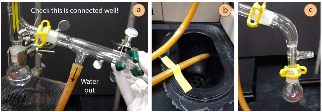
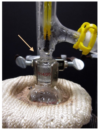
Safety note: Be sure that there is a secure connection between the distilling flask and the three-way adapter (as pointed to in Figure 5.24a). This connection can be enforced by a strong hold on the condenser. If there is an opening between the distilling flask and adapter, vapors can escape. Being so close to the heat source, the vapors have the greatest potential to ignite at this location. - Connect the rubber hose attached to the lower arm of the condenser to the water spigot and allow the hose attached to the upper arm of the condenser to drain to the sink. The hoses may point either up or down. If the drainage hose just barely reaches the sink, secure it with lab tape (Figure 5.24b) so that it does not spray all over the benchtop.
- Connect a vacuum adapter to the end of the condenser with a plastic clip. Then use another clip to connect a round bottomed flask (receiving flask) that has enough volume to just hold the quantity of expected distillate (Figure 5.24c). Variations in receiving flasks are shown in a later section.
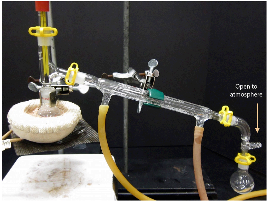
- A completed distillation apparatus is shown in Figure 5.25. No parts should be able to jiggle or they are not adequately clamped. Although it may appear to be a closed system (which would be dangerous to heat), the system is actually open to the atmosphere at the arm in the vacuum adapter.
- Prepare the heat source beneath the flask:
- Heating mantles, oil baths, and heat guns are recommended heat sources for distillation. Bunsen burners are not recommended for use with volatile organic compounds, but may be used in some situations at the discretion of the instructor.
- Position the heat source beneath the flask, using an adjustable platform that allows for some mechanism by which the heat can be lowered and removed at the end of the distillation. A ring clamp and wire mesh platform is a good way to hold a heating mantle or oil bath beneath the flask.
Begin Distilling
- When ready to begin the distillation, start circulating water in the condenser. The flow of water should be more than a trickle, but should not be so strong that the hose flops around from the high water pressure.
- Since it is so important, check once again that there is a secure connection between the distilling flask and the three-way adapter (as indicated in Figure 5.26). If there is a crack between the distilling flask and adapter, vapors can escape the apparatus and possibly ignite!
- Begin heating the flask. Depending on the size of the flask and the necessary temperature, the liquid may start boiling between 1-20 minutes. Condensation will eventually be seen on the sides of the flask, but the reading on the thermometer will not increase until the vapors immerse the thermometer bulb. It is not unusual that the liquid boils while the thermometer remains at room temperature.
- Eventually condensation should be seen in the three-way adapter, and the thermometer temperature will rise. Not all compounds produce obvious droplets (as in Figure 5.26), but condensation may be seen by close inspection and subtle movement near the thermometer.
Safety note: If the compound's boiling point is \(> 75^\text{o} \text{C}\), the three-way adapter will be hot to the touch! - Eventually a droplet may be seen traveling down the length of the condenser and liquid will begin to collect in the receiving flask. An appropriate distillation collects distillate at a rate of 1 drop per second. Distilling at too fast a rate prevents proper equilibration between liquid and gas phases, and results in poor separation.
Although a slow distillation is necessary, heating the solution such that nothing is dripping into the receiving flask simply wastes time. There is no reason to heat so gradually that nothing distills.

Record the Temperature and Pressure
- Pay attention to the temperature on the thermometer throughout the entire time that liquid is distilling. Record the temperature when it has plateaued, or the highest temperature seen. If you know a mixture is distilling, record the temperature range over which liquid is actively dripping into the receiving flask.
The thermometer bulb must be fully immersed in vapors to register an accurate temperature (Figure 5.27d). Therefore, the temperature near the very beginning and end of the distillation tends to be inaccurate. Only record temperatures that correspond to active distillation and full immersion of the thermometer with vapor. - As boiling points are so dependent on temperature, also record the barometric pressure.
Stop Distilling
- Cease the distillation when one of the following takes place:
- If the liquid is nearly gone in the distilling flask.
Safety note: It is unsafe to distill a flask to dryness as side reactions can occur when components are concentrated. This is especially dangerous with compounds that can form peroxides,\(^9\) as these can become explosive when reacting with concentrated solutions. Additionally, when the entire sample is in the gas phase, the system is not longer restricted to the boiling point of the liquid and may reach dangerous temperatures. - If the thermometer temperature was higher during the distillation but has dropped significantly. This normally corresponds to a lull between distilling two components, and means that one component has essentially completed distilling.
- If the thermometer temperature has a dramatic spike. This normally corresponds to the beginning of distillation of a higher boiling component, and would contaminate the distillate if allowed to continue.
- If anything surprising or unusual happens, such as thick smoke, darkening/thickening in the distilling flask, or uncontrollable bumping.
- If the liquid is nearly gone in the distilling flask.
- To stop the distillation, lower and remove the heat source from the round bottomed flask (Figure 5.28a).
- Keep water circulating in the condenser until the liquid in the distilling flask is just warm to the touch, then turn off the condenser water and disassemble the apparatus. After a few minutes of air cooling, cooling of the flask can be hastened by immersion with a container of tap water (Figure 5.28b).
Simple Distillation Summary
|
Assembly tips Fill the distilling flask with sample 1/3-1/2 full. Always use an extension clamp on the distilling flask. Add a few boiling stones or stir bar to flask. Position the thermometer bulb just below the arm of the three-way adapter, where vapors turn toward the condenser. |
Wet condenser hoses with water before attaching. Connect the condenser hoses such that water flow uphill: bring water from the faucet into the lower arm, and drain out the upper arm. Be sure all of the connections are secure (especially between the distilling flask and 3-way adapter: potential of fire!) |
Begin distillation Turn on the condenser water. Apply the heat source to the distilling flask. Collect distillate at a rate of 1 drop per second. Record the temperature where liquid is actively distilling and thermometer bulb is immersed. Record the pressure. |
Cease distillation Stop the distillation when the temperature changes dramatically or if the distilling flask is nearly empty (never distill to dryness!) Lower and remove the heat source, but keep water circulating until the flask is just warm to the touch. |
Variations
A few variations of the simple distillation setup are commonly encountered:
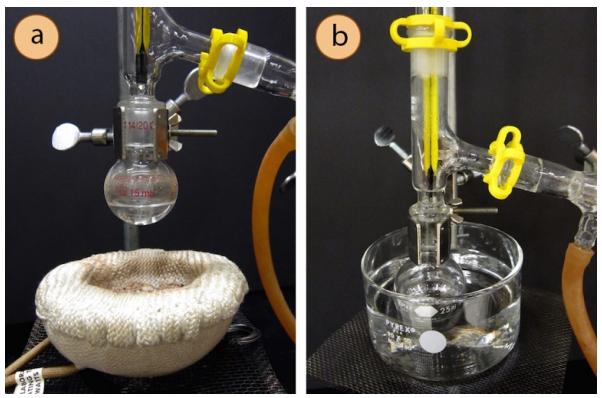
- When a certain volume of distillate is desired, the distillate may be collected directly into a graduated cylinder (Figure 5.30a). This method allows for cylinders to be easily exchanged, perhaps for analysis of different fractions of distillate.
- The receiving flask is sometimes submerged in an ice bath (Figure 5.30b), particularly when the distillate is volatile (has a boiling point \(< 100^\text{o} \text{C}\)). Any container can be used for the ice bath. Be sure to use a combination of both ice and water in the bath, as ice alone does not have as good contact with the flask as a slurry of ice-water.
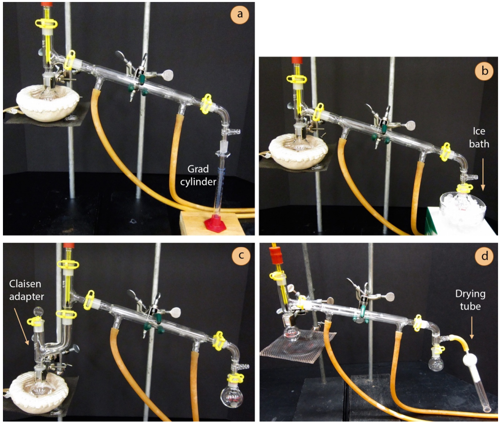
- A Claisen adapter (Figure 5.30c) may be inserted between the round bottomed flask and three-way adapter in anticipation of foaming or bumping. The Claisen adapter acts as a buffer so that uncontrolled activity in the distilling flask does not immediately carry over to the receiving flask. If the solution foams, the Claisen adapter provides time to adjust the heat without ruining the distillate. A Claisen adapter also potentially allows for more vaporization-condensation events (or theoretical plates).
- For distillation of water-sensitive materials, glassware can be oven or flame dried, and a drying tube can be attached to the vacuum adapter (Figure 5.30d).
Troubleshooting
Boiling, but Temperature isn't Rising/How to Insulate
It is not uncommon for new organic chemistry students to expect the temperature to rise on the thermometer the very moment boiling is seen in the distilling flask. Students should remember that the thermometer measures the temperature at the location of the bulb, which is a distance away from the boiling liquid. Therefore, when a solution begins to boil, it may still take a while for the thermometer to register anything other than room temperature.
It is important to record a temperature only when the thermometer bulb is fully engulfed by vapors. Figure 5.31a shows a solution that is boiling but not yet distilling - the temperature at this point would not represent the boiling point of the liquid. Figure 5.31b shows an actively distilling solution, and notice that the thermometer bulb is completely enveloped in vapors and condensation; the temperature at this point would correspond to the boiling point of the solution.
For high-boiling liquids, it may be difficult for vapors to reach the condenser as they too quickly are cooled by the glassware which is in contact with the air in the room. It may be helpful to insulate the distilling flask and three-way adapter to better retain heat and allow the sample to remain in the gas phase longer.
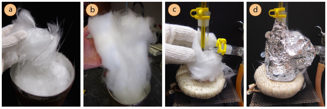
To insulate a portion of the distillation, wrap the parts prior to the condenser with glass wool (Figure 5.32c), then secure with an outer wrapping of aluminum foil (Figure 5.32d). A small gap can be left in the insulation in order to "peek in" on activity inside the apparatus. Glass wool has an appearance similar to cotton, but unlike cotton is not flammable so is useful as an insulating material when an apparatus is to be heated. Glass wool comes in two forms: a fibrous form and a cottony form. The fibrous form (Figure 5.32a) has tiny fibers that can become embedded in skin in the most painful way, similar to several simultaneous paper cuts. This type of glass wool should not be manipulated with bare hands, but only when wearing thick gloves. The more cotton-like glass wool (Figure 5.32b), however, does not hurt when handling with bare hands.
If glass wool is unavailable, aluminum foil can be used alone to insulate a portion of the distillation. It will not insulate well if the foil is wrapped too tightly to the glass, but works well if a small pocket of air is allowed between the foil and glass.
If the expected boiling point of the compound to be distilled is quite high \(\left( > 150^\text{o} \text{C} \right)\) and distillation continues to be difficult, vacuum distillation might be attempted.
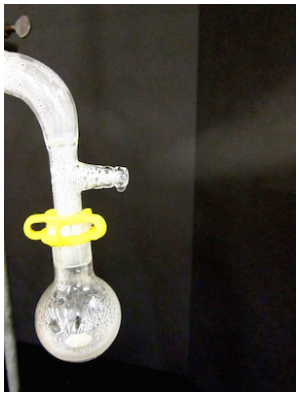
Vapor is Escaping from Vacuum Adapter
If vapor is noticed escaping out of the vacuum adapter like a tea kettle, the condenser is not doing a good enough job of trapping the gas (Figure 5.33). Reasons for this may be that you have forgotten to turn on the water in the condenser, the water stream is too weak, or the heating is too vigorous.
\(^8\)Prices were found in the Chemglass catalog in March 2016.
\(^9\)Certain compounds (e.g. ethers, dioxanes, tetrahydrofuran) are well known to form peroxides when left in contact with air over a period of time. However, many compounds are somewhat susceptible to peroxide formation, including compounds with allylic hydrogen atoms (e.g. cyclohexene). A more complete listing of compounds that form peroxides can be found in: Handbook of Chemistry and Physics, CRC Press, 84\(^\text{th}\) edition, 2003-2004, 16-6.