
3.6: Optical activity
- Page ID
- 531787

\( \newcommand{\vecs}[1]{\overset { \scriptstyle \rightharpoonup} {\mathbf{#1}} } \)
\( \newcommand{\vecd}[1]{\overset{-\!-\!\rightharpoonup}{\vphantom{a}\smash {#1}}} \)
\( \newcommand{\dsum}{\displaystyle\sum\limits} \)
\( \newcommand{\dint}{\displaystyle\int\limits} \)
\( \newcommand{\dlim}{\displaystyle\lim\limits} \)
\( \newcommand{\id}{\mathrm{id}}\) \( \newcommand{\Span}{\mathrm{span}}\)
( \newcommand{\kernel}{\mathrm{null}\,}\) \( \newcommand{\range}{\mathrm{range}\,}\)
\( \newcommand{\RealPart}{\mathrm{Re}}\) \( \newcommand{\ImaginaryPart}{\mathrm{Im}}\)
\( \newcommand{\Argument}{\mathrm{Arg}}\) \( \newcommand{\norm}[1]{\| #1 \|}\)
\( \newcommand{\inner}[2]{\langle #1, #2 \rangle}\)
\( \newcommand{\Span}{\mathrm{span}}\)
\( \newcommand{\id}{\mathrm{id}}\)
\( \newcommand{\Span}{\mathrm{span}}\)
\( \newcommand{\kernel}{\mathrm{null}\,}\)
\( \newcommand{\range}{\mathrm{range}\,}\)
\( \newcommand{\RealPart}{\mathrm{Re}}\)
\( \newcommand{\ImaginaryPart}{\mathrm{Im}}\)
\( \newcommand{\Argument}{\mathrm{Arg}}\)
\( \newcommand{\norm}[1]{\| #1 \|}\)
\( \newcommand{\inner}[2]{\langle #1, #2 \rangle}\)
\( \newcommand{\Span}{\mathrm{span}}\) \( \newcommand{\AA}{\unicode[.8,0]{x212B}}\)
\( \newcommand{\vectorA}[1]{\vec{#1}} % arrow\)
\( \newcommand{\vectorAt}[1]{\vec{\text{#1}}} % arrow\)
\( \newcommand{\vectorB}[1]{\overset { \scriptstyle \rightharpoonup} {\mathbf{#1}} } \)
\( \newcommand{\vectorC}[1]{\textbf{#1}} \)
\( \newcommand{\vectorD}[1]{\overrightarrow{#1}} \)
\( \newcommand{\vectorDt}[1]{\overrightarrow{\text{#1}}} \)
\( \newcommand{\vectE}[1]{\overset{-\!-\!\rightharpoonup}{\vphantom{a}\smash{\mathbf {#1}}}} \)
\( \newcommand{\vecs}[1]{\overset { \scriptstyle \rightharpoonup} {\mathbf{#1}} } \)
\(\newcommand{\longvect}{\overrightarrow}\)
\( \newcommand{\vecd}[1]{\overset{-\!-\!\rightharpoonup}{\vphantom{a}\smash {#1}}} \)
\(\newcommand{\avec}{\mathbf a}\) \(\newcommand{\bvec}{\mathbf b}\) \(\newcommand{\cvec}{\mathbf c}\) \(\newcommand{\dvec}{\mathbf d}\) \(\newcommand{\dtil}{\widetilde{\mathbf d}}\) \(\newcommand{\evec}{\mathbf e}\) \(\newcommand{\fvec}{\mathbf f}\) \(\newcommand{\nvec}{\mathbf n}\) \(\newcommand{\pvec}{\mathbf p}\) \(\newcommand{\qvec}{\mathbf q}\) \(\newcommand{\svec}{\mathbf s}\) \(\newcommand{\tvec}{\mathbf t}\) \(\newcommand{\uvec}{\mathbf u}\) \(\newcommand{\vvec}{\mathbf v}\) \(\newcommand{\wvec}{\mathbf w}\) \(\newcommand{\xvec}{\mathbf x}\) \(\newcommand{\yvec}{\mathbf y}\) \(\newcommand{\zvec}{\mathbf z}\) \(\newcommand{\rvec}{\mathbf r}\) \(\newcommand{\mvec}{\mathbf m}\) \(\newcommand{\zerovec}{\mathbf 0}\) \(\newcommand{\onevec}{\mathbf 1}\) \(\newcommand{\real}{\mathbb R}\) \(\newcommand{\twovec}[2]{\left[\begin{array}{r}#1 \\ #2 \end{array}\right]}\) \(\newcommand{\ctwovec}[2]{\left[\begin{array}{c}#1 \\ #2 \end{array}\right]}\) \(\newcommand{\threevec}[3]{\left[\begin{array}{r}#1 \\ #2 \\ #3 \end{array}\right]}\) \(\newcommand{\cthreevec}[3]{\left[\begin{array}{c}#1 \\ #2 \\ #3 \end{array}\right]}\) \(\newcommand{\fourvec}[4]{\left[\begin{array}{r}#1 \\ #2 \\ #3 \\ #4 \end{array}\right]}\) \(\newcommand{\cfourvec}[4]{\left[\begin{array}{c}#1 \\ #2 \\ #3 \\ #4 \end{array}\right]}\) \(\newcommand{\fivevec}[5]{\left[\begin{array}{r}#1 \\ #2 \\ #3 \\ #4 \\ #5 \\ \end{array}\right]}\) \(\newcommand{\cfivevec}[5]{\left[\begin{array}{c}#1 \\ #2 \\ #3 \\ #4 \\ #5 \\ \end{array}\right]}\) \(\newcommand{\mattwo}[4]{\left[\begin{array}{rr}#1 \amp #2 \\ #3 \amp #4 \\ \end{array}\right]}\) \(\newcommand{\laspan}[1]{\text{Span}\{#1\}}\) \(\newcommand{\bcal}{\cal B}\) \(\newcommand{\ccal}{\cal C}\) \(\newcommand{\scal}{\cal S}\) \(\newcommand{\wcal}{\cal W}\) \(\newcommand{\ecal}{\cal E}\) \(\newcommand{\coords}[2]{\left\{#1\right\}_{#2}}\) \(\newcommand{\gray}[1]{\color{gray}{#1}}\) \(\newcommand{\lgray}[1]{\color{lightgray}{#1}}\) \(\newcommand{\rank}{\operatorname{rank}}\) \(\newcommand{\row}{\text{Row}}\) \(\newcommand{\col}{\text{Col}}\) \(\renewcommand{\row}{\text{Row}}\) \(\newcommand{\nul}{\text{Nul}}\) \(\newcommand{\var}{\text{Var}}\) \(\newcommand{\corr}{\text{corr}}\) \(\newcommand{\len}[1]{\left|#1\right|}\) \(\newcommand{\bbar}{\overline{\bvec}}\) \(\newcommand{\bhat}{\widehat{\bvec}}\) \(\newcommand{\bperp}{\bvec^\perp}\) \(\newcommand{\xhat}{\widehat{\xvec}}\) \(\newcommand{\vhat}{\widehat{\vvec}}\) \(\newcommand{\uhat}{\widehat{\uvec}}\) \(\newcommand{\what}{\widehat{\wvec}}\) \(\newcommand{\Sighat}{\widehat{\Sigma}}\) \(\newcommand{\lt}{<}\) \(\newcommand{\gt}{>}\) \(\newcommand{\amp}{&}\) \(\definecolor{fillinmathshade}{gray}{0.9}\)Chirality of light
Light, like all electromagnetic radiations, is an oscillating electric field and magnetic field, perpendicular to each other and perpendicular to the axis of propagation of the wave, as simulated in Figure \(\PageIndex{1}\) b). Electric and magnetic fields oscillate in all directions perpendicular to the direction of their propagation. Such light is called unpolarized light. When unpolarized light is passed through a filter, called a polarizer, it emerges with electric field oscillation in one plane, say the yx-plane, and the magnetic field perpendicular to it, say in the zx-plane, as simulated in Figure \(\PageIndex{1}\) b).
 The light with an electric field oscillating in one plane is called linearly polarized light (LPL) or plane-polarized light.
The polarizer can be viewed as a slit that allows the electric field to pass through it if it is parallel to its orientation. For example, the electric field represented by the blue wave in the illustration on the right margin is parallel to the slit and passes through it, whereas the red one is blocked because it is not parallel to the slit (Copyright: Jcwf, CC0, via Wikimedia Commons). If a second polarizer is placed next, it will allow the radiation to pass through with full brightness if its slit is aligned with the plane of the plane-polarized light, otherwise it will dim the light when it is out of alighment and completely block it when it is perpendicular, as demonstrated in the simulation on the left margin (Copyright; Rogilbert, Public domain, via Wikimedia Commons).
 a) Left circularly polarized light
 b) Linearly polarized light
 c) Right circularly polarized light
Another form of polarized light is circularly polarized light.
Circularly polarized light has an electric field of constant magnitude that rotates, either clockwise or counterclockwise, as the wave propagates. If the electric field is rotating counterclockwise, it is left circularly polarized light, and if rotating clockwise, it is right circularly polarized light.
Simulations in Figure \(\PageIndex{1}\) a) and c) illustrate the electric field component of left and right circularly polarized lights. The left and right circularly polarized lights are nonsuperposable mirror images of each other, similar to left- and right-handed springs, as shown in Figure 3.4.2.
 Circularly polarized light is chiral, like chiral objects, which have nonsuperposable mirror images.
Circularly polarized light can be resolved into two linearly polarized components, as shown by the black helical curve in the simulation on the right margin, which is resolved into two linear sign waves shown by red and blue curves (Copyright; de:Benutzer:Averse, CC BY-SA 2.0, via Wikimedia Commons). Similarly, adding the left and right circularly polarized lights, as shown in Figure \(\PageIndex{1}\) a) and c), results in linearly polarized light as shown in Figure \(\PageIndex{1}\) c). In other words, linearly polarized light can be viewed as composed of two equal left and right circularly polarized components, which are nonsuperposable mirror images of each other.
Linearly polarized light is chiral, composed of equal left and right circularly polarized components, which are nonsuperposable mirror images of each other.
Interaction of plane polarized light with matter
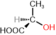
 A chiral object and its nonsupposable mirror object are called enantiomorphs. A chiral molecule and its nonsuperposable mirror molecule are enantiomers. Enantiomers and enantiomorphs exhibit the same physical and chemical properties, except when they interact with another chiral thing. For example, a tennis ball, which is achiral, fits equally well on chiral left and right hands, but a chiral left glove fits on the left hand and a right glove on the right hand, not the other way around. Similarly, a model of the chiral amino acid L-alanine fits in the left hand, but its enantiomer D-alanine fits the same way in right hand, as illustrated in the figure on the left margin (Copyright; Original: Unknown Vector: -- πϵρήλιο, Public domain, via Wikimedia Commons).
 Plane polarized light is chiral. When light passes from a vacuum to another medium, its speed slows down. When the medium is chiral, the left- and right-circularly polarized components of the plane-polarized light slow down unequally. Therefore, the plane of plane-polarized light rotates either clockwise or counterclockwise as it traverses a chiral medium, as shown in the simulation on the right margin (Copyright Jacopo Bertolotti, CC0, via Wikimedia Commons). If the left circularly polarized component is slower, the plane of the emerging light rotates clockwise, and if the right component is slower, it rotates counterclockwise.
A chiral medium that rotates the plane of the plane polarized light clockwise is called dextrorotatory (d) or (+), and the one that rotates it counterclockwise is called levorotatory (l) or (-). The ability of chiral compounds to rotate the plane of plane-polarized light is called optical activity. Chiral compounds are optically active, and achiral compounds are optically inactive.
History of optica activity
Rotation of linearly polarized light as it passes through a quartz crystal was first observed in 1811. It is called optical activity. It was discovered in 1820 that quartz has two types of crystals, which are nonsuperposable mirror images of each other. One rotates the plane-polarized light clockwise, and the other rotates it by the same degree but counterclockwise. In 1815, Jean Baptiste Biot observed that some organic liquids or their vapors also rotate the plane of the plane polarized light. In 1822, Fresnel found that the rotation of light is related to the two components of light being affected differently in an optically active medium.
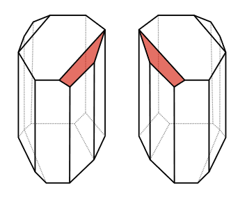 It was observed that tartaric acid salts derived from living sources were optically active, whereas a synthetic one with the same composition was optically inactive. In 1849, Louis Pasteur recrystallized ammonium potassium tartrate and separated two types of crystals by hand-picking, which were enantiomorphs, as shown in the figure on the right margin (Copyright; Tom Murphy VII (Brighterorange), Public domain, via Wikimedia Commons). The original mixture was optically inactive, but upon dissolving the crystals in water, one type exhibited dextrorotatory properties, and its enantiomorph showed levorotatory properties. Their 1:1 mixture was optically inactive. Pasteur concluded that the molecules that constitute the enantiomorphic crystals were asymmetric forms that resembled each other, much like the left and right hands. Pasteur's discovery is considered the beginning of chirality in organic chemistry.
van 't Hoff and Le Bel proposed in 1849 that four single bonds of \(\ce{C}\) are oriented as if they are directed towards the corner of a tetrahedron. If the four substituents are different, they can be arranged in two different ways, which will be mirror images of each other. It proved the Pasture's conclusion about asymmetric forms of molecules responsible for the optical activity.
Measuring optical activity
The instrument used to measure optical activity is called a polarimeter, as illustrated in Figure \(\PageIndex{2}\).
A polarimeter typically features a source of light, usually a sodium lamp that emits unpolarized light of a wavelength of 589 nm, known as the D line of sodium. A polarizer converts it into linearly polarized light, which is then passed through a sample tube containing a solution of the test sample. An analyzer measures the rotation of the plane of the light by rotating it clockwise or counterclockwise until it transmits the brightest light. The angle or rotation (\(\alpha\)) is measured in degrees (\(^o\)) and assighned dextrorotatory (+) for a clockwise rotation, or levorotatory (-) for a counterclockwise rotation.

he angle or rotation (\(\alpha\)) is called observed rotation. The observed rotation depends on the concentration of the sample (\(c\)), the path length of the light through the sample (\(l\)), the wavelength (\(\lambda\)) of the light used, and the temperature (\(T\)).
When the concentration is fixed to 1 g/mL (or density of the pure sample in g/mL) and path length to 1 dm, the observed rotation is called specific rotation [\(\alpha\)].
Usually, the wavelength (\(\lambda\)) is the sodium D line 589 nm and the temperature (T) is room temperature, which are shown as subscript and superscript: \([\alpha]^{T}_{\lambda}\). The following formula relates these parameters.
\[[\alpha]^{T}_{\lambda} = \frac{\alpha (in degree)}{l \text {(in dm)}}\times {c (in \frac{g}{mL})} \nonumber \]
The specific rotation is a characteristic physical property of chiral compounds. If one enantiomer is dextrorotatory, the other is levorotatory to the same degree, as shown in the examples in Figure \(\PageIndex{3}\).


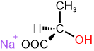
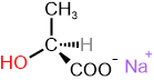
S and R define the absolute configuration of the chirality center, and dextrorotatory (+) or levorotatory (-) is an experimental property of the compound. A compound with S configuration may be dextrorotatory (+) or levorotatory (-), the same for R configuration. For example, (S)-lactic acid is dextrorotatory (+), and its salt (S)-sodium lactate is levorotatory (-), as shown in Figure \(\PageIndex{3}\). Similarly, it is essential to note that the specific rotation varies with temperature. For example, (S)-aspartic acid is levorotatory at 20 \(^o\)C, but it is dextrorotatory at 100 \(^o\)C.
A solution of 3.00 g of table sugar (sucrose) dissolved in 100 mL of water, when placed in a 10.0 cm sample tube, shows \(\alpha\) = +1.99\(^o\) when the sodium D line is used at 20\(^o\). What is the specific rotation of succrose?
Solution
Given: Concentration = \(\frac{3.00\text{ g}}{100 \text{ mL}} = 0.03 \frac{g}{mL}\), \(\alpha\) = +1.99^o\), path lenght \(l = 10 \text { dm}\), \([\alpha]^{T}_{\lambda}\) = ?
Calculations:
\[[\alpha]^{T}_{\lambda} = \frac{\alpha (^o)}{l \text {(dm)}}\times {c (\frac{g}{mL})} = \frac{1.99^o}{10\text {dm}}\times {0.03 \frac{g}{mL}} = +66.3\nonumber \]
Enantiomeric excess
Enantiomers have equal specific rotation ( \([\alpha]^{T}_{\lambda}\)) but with opposite sign. Suppose d- isomer is 100%, its specific rotation is \([\alpha]^{T}_{\lambda}\). If \(x%\) l-isomer is in a mixture, it will cancel the activity of an equal amount of d-isomer, leaving \((100 -2x)\%\) enantiomeric excess (\(\%ee\)) of d-isomer, which will show the specific rotation of the mixture. The enantiomeric excess (\(\%ee\)) can be calculated by the following formula, provided \(x%\) of l-isomer is less than 50%.
\[\%ee = (100 -2x)\%= \frac{[\alpha]^{T}_{\lambda}\text{ (mixture)}}{[\alpha]^{T}_{\lambda}\text{ (pure)}}\times {100}\%\nonumber\]
,where \(x\)% is the enantiomer less than 50% and \([\alpha]^{T}_{\lambda}\text{ (pure)}\) is for the enantiomer more than 50% in the mixture. If the specific rotation of the mixture and the pure enantiomer are known, the above formula allows calculating the percentage composition of the mixture.
Mixing enantiomers diminishes the optical activity until it reaches a 50:50 mixture of enantiomers, which is optically inactive and referred to as a racemic mixture.
(+)-butan-2-ol has \([\alpha]^{25}_{D}\) +13.52\(^o\). Suppose a mixture of + and - enantiomers of butan-2-ol shows specific rotation of +10.0\(^o\), what is the enantiomeric excess of (+)-butan-2-ol, and what is the percentage composition of the mixture with respect to (+) and (-)butan-2-ol?
Solution
Given: \([\alpha]^{T}_{\lambda}\text{ ((+)-butan-2-ol)} = +13.52^o\), \([\alpha]^{T}_{\lambda}\text{ (mixture)} = +10.0^o\), enantiomeric excess of enantiomeric excess of (+)-butan-2-ol (\(\%ee\) = ?, %(-)-butan-2-ol = ? %(+)-butan-2-ol = ?
Calculations:
\[\%ee = (100 -2\text{((-)-butan-2-ol)}\%= \frac{[\alpha]^{T}_{\lambda}\text{ (mixture)}}{[\alpha]^{T}_{\lambda}\text{ (pure (+)-butan-2-ol)}}\times {100}\% = \frac{10.0\text{^o}}{13.52\text{\^o}}\times {100}\% = 74.0\% \nonumber\]
\[(100 -2(\text{(-)-butan-2-ol)}\%=74.0\% \implies \text{(-)-butan-2-ol)}\% = \frac{74.0-100}{-2} = 13\% \nonumber\]
\[\text{(+)-butan-2-ol)}\% = (100\% - \text{(-)-butan-2-ol)}\%) = 100\% - 13\% = 87\%\nonumber\]