17.8: Galvanic Cells
- Page ID
- 49558

\( \newcommand{\vecs}[1]{\overset { \scriptstyle \rightharpoonup} {\mathbf{#1}} } \)
\( \newcommand{\vecd}[1]{\overset{-\!-\!\rightharpoonup}{\vphantom{a}\smash {#1}}} \)
\( \newcommand{\dsum}{\displaystyle\sum\limits} \)
\( \newcommand{\dint}{\displaystyle\int\limits} \)
\( \newcommand{\dlim}{\displaystyle\lim\limits} \)
\( \newcommand{\id}{\mathrm{id}}\) \( \newcommand{\Span}{\mathrm{span}}\)
( \newcommand{\kernel}{\mathrm{null}\,}\) \( \newcommand{\range}{\mathrm{range}\,}\)
\( \newcommand{\RealPart}{\mathrm{Re}}\) \( \newcommand{\ImaginaryPart}{\mathrm{Im}}\)
\( \newcommand{\Argument}{\mathrm{Arg}}\) \( \newcommand{\norm}[1]{\| #1 \|}\)
\( \newcommand{\inner}[2]{\langle #1, #2 \rangle}\)
\( \newcommand{\Span}{\mathrm{span}}\)
\( \newcommand{\id}{\mathrm{id}}\)
\( \newcommand{\Span}{\mathrm{span}}\)
\( \newcommand{\kernel}{\mathrm{null}\,}\)
\( \newcommand{\range}{\mathrm{range}\,}\)
\( \newcommand{\RealPart}{\mathrm{Re}}\)
\( \newcommand{\ImaginaryPart}{\mathrm{Im}}\)
\( \newcommand{\Argument}{\mathrm{Arg}}\)
\( \newcommand{\norm}[1]{\| #1 \|}\)
\( \newcommand{\inner}[2]{\langle #1, #2 \rangle}\)
\( \newcommand{\Span}{\mathrm{span}}\) \( \newcommand{\AA}{\unicode[.8,0]{x212B}}\)
\( \newcommand{\vectorA}[1]{\vec{#1}} % arrow\)
\( \newcommand{\vectorAt}[1]{\vec{\text{#1}}} % arrow\)
\( \newcommand{\vectorB}[1]{\overset { \scriptstyle \rightharpoonup} {\mathbf{#1}} } \)
\( \newcommand{\vectorC}[1]{\textbf{#1}} \)
\( \newcommand{\vectorD}[1]{\overrightarrow{#1}} \)
\( \newcommand{\vectorDt}[1]{\overrightarrow{\text{#1}}} \)
\( \newcommand{\vectE}[1]{\overset{-\!-\!\rightharpoonup}{\vphantom{a}\smash{\mathbf {#1}}}} \)
\( \newcommand{\vecs}[1]{\overset { \scriptstyle \rightharpoonup} {\mathbf{#1}} } \)
\(\newcommand{\longvect}{\overrightarrow}\)
\( \newcommand{\vecd}[1]{\overset{-\!-\!\rightharpoonup}{\vphantom{a}\smash {#1}}} \)
\(\newcommand{\avec}{\mathbf a}\) \(\newcommand{\bvec}{\mathbf b}\) \(\newcommand{\cvec}{\mathbf c}\) \(\newcommand{\dvec}{\mathbf d}\) \(\newcommand{\dtil}{\widetilde{\mathbf d}}\) \(\newcommand{\evec}{\mathbf e}\) \(\newcommand{\fvec}{\mathbf f}\) \(\newcommand{\nvec}{\mathbf n}\) \(\newcommand{\pvec}{\mathbf p}\) \(\newcommand{\qvec}{\mathbf q}\) \(\newcommand{\svec}{\mathbf s}\) \(\newcommand{\tvec}{\mathbf t}\) \(\newcommand{\uvec}{\mathbf u}\) \(\newcommand{\vvec}{\mathbf v}\) \(\newcommand{\wvec}{\mathbf w}\) \(\newcommand{\xvec}{\mathbf x}\) \(\newcommand{\yvec}{\mathbf y}\) \(\newcommand{\zvec}{\mathbf z}\) \(\newcommand{\rvec}{\mathbf r}\) \(\newcommand{\mvec}{\mathbf m}\) \(\newcommand{\zerovec}{\mathbf 0}\) \(\newcommand{\onevec}{\mathbf 1}\) \(\newcommand{\real}{\mathbb R}\) \(\newcommand{\twovec}[2]{\left[\begin{array}{r}#1 \\ #2 \end{array}\right]}\) \(\newcommand{\ctwovec}[2]{\left[\begin{array}{c}#1 \\ #2 \end{array}\right]}\) \(\newcommand{\threevec}[3]{\left[\begin{array}{r}#1 \\ #2 \\ #3 \end{array}\right]}\) \(\newcommand{\cthreevec}[3]{\left[\begin{array}{c}#1 \\ #2 \\ #3 \end{array}\right]}\) \(\newcommand{\fourvec}[4]{\left[\begin{array}{r}#1 \\ #2 \\ #3 \\ #4 \end{array}\right]}\) \(\newcommand{\cfourvec}[4]{\left[\begin{array}{c}#1 \\ #2 \\ #3 \\ #4 \end{array}\right]}\) \(\newcommand{\fivevec}[5]{\left[\begin{array}{r}#1 \\ #2 \\ #3 \\ #4 \\ #5 \\ \end{array}\right]}\) \(\newcommand{\cfivevec}[5]{\left[\begin{array}{c}#1 \\ #2 \\ #3 \\ #4 \\ #5 \\ \end{array}\right]}\) \(\newcommand{\mattwo}[4]{\left[\begin{array}{rr}#1 \amp #2 \\ #3 \amp #4 \\ \end{array}\right]}\) \(\newcommand{\laspan}[1]{\text{Span}\{#1\}}\) \(\newcommand{\bcal}{\cal B}\) \(\newcommand{\ccal}{\cal C}\) \(\newcommand{\scal}{\cal S}\) \(\newcommand{\wcal}{\cal W}\) \(\newcommand{\ecal}{\cal E}\) \(\newcommand{\coords}[2]{\left\{#1\right\}_{#2}}\) \(\newcommand{\gray}[1]{\color{gray}{#1}}\) \(\newcommand{\lgray}[1]{\color{lightgray}{#1}}\) \(\newcommand{\rank}{\operatorname{rank}}\) \(\newcommand{\row}{\text{Row}}\) \(\newcommand{\col}{\text{Col}}\) \(\renewcommand{\row}{\text{Row}}\) \(\newcommand{\nul}{\text{Nul}}\) \(\newcommand{\var}{\text{Var}}\) \(\newcommand{\corr}{\text{corr}}\) \(\newcommand{\len}[1]{\left|#1\right|}\) \(\newcommand{\bbar}{\overline{\bvec}}\) \(\newcommand{\bhat}{\widehat{\bvec}}\) \(\newcommand{\bperp}{\bvec^\perp}\) \(\newcommand{\xhat}{\widehat{\xvec}}\) \(\newcommand{\vhat}{\widehat{\vvec}}\) \(\newcommand{\uhat}{\widehat{\uvec}}\) \(\newcommand{\what}{\widehat{\wvec}}\) \(\newcommand{\Sighat}{\widehat{\Sigma}}\) \(\newcommand{\lt}{<}\) \(\newcommand{\gt}{>}\) \(\newcommand{\amp}{&}\) \(\definecolor{fillinmathshade}{gray}{0.9}\)In an electrolytic cell electrical energy is consumed and an otherwise spontaneous redox reaction is reversed. A galvanic cell, on the other hand, produces electrical energy as a result of a spontaneous redox process. The electron transfer characteristic of such a process is made to occur in two separate half-cells. Electrons released during an oxidation half-equation must flow through a wire or other external circuit before they can be accepted in a reduction half-equation. Consequently an electrical current is made to flow.
A typical galvanic cell, the Daniell cell, was used to power telegraphs 100 years ago. This cell is based on the spontaneous redox reaction
\[\text{Zn}(s) + \text{Cu}^{2+}(aq) \rightarrow \text{Zn}^{2+}(aq) + \text{Cu}(s)\label{1} \]
(You can verify that this reaction is spontaneous by dipping a piece of zinc metal in a copper sulfate solution. In a short time the surface of the zinc will become plated with red-brown copper metal.) The half-equations
\[\text{Zn}(s) \rightarrow \text{Zn}^{2+}(aq) + \text{2}e^{-}\label{2} \]
\[\text{Cu}^{2+}(aq) + \text{2}e^{-} \rightarrow \text{Cu}(s)\label{3} \]
indicate that for each mole of zinc which is oxidized and goes into solution as zinc ions, 2 mol electrons are transferred to copper ions, converting them to copper atoms.
To produce electrical current we must prevent the Zn(s) from contacting the Cu2+(aq) ions and transferring the electrons directly. This is done in the Daniell cell by pouring a concentrated copper sulfate solution into the bottom of a glass jar and then carefully pouring a layer of less concentrated zinc sulfate solution above it. Because it contains less solute per unit volume, the zinc sulfate solution is less dense. It floats on the copper sulfate and does not mix with it. Therefore a copper electrode placed in the bottom of the jar contacts only Cu2+(aq) ions, and a zinc electrode suspended in the zinc sulfate solution contacts only Zn2+(aq) ions.
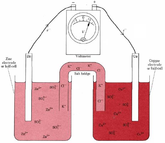
In the laboratory it is more convenient to set up a cell based on the Zn + Cu2+ reaction, as shown in Figure \(\PageIndex{1}\). Two electrodes or half-cells are separated by a salt bridge. This contains an electrolyte, KCl, so that current can flow from one half-cell to the other, but the contents of the two half-cells cannot mix. The left-hand electrode in Figure \(\PageIndex{1}\) is a Zn rod dipping in a solution of ZnSO4. Thus both components of the Zn2+/Zn redox couple are present, and the metal electrode can conduct electrons produced by Eq. \(\ref{2}\) to the wire in the external circuit. Since oxidation of Zn to Zn2+ occurs at the left-hand electrode, this electrode is the anode.
The right-hand electrode is a strip of Cu dipping in a solution of CuSO4. Here both components of the Cu2+/Cu redox couple are present, and Eq. \(\ref3\) can occur. Electrons supplied by the external circuit are conducted through Cu to the electrode surface, where they combine with Cu2+ ions to produce more Cu. Since reduction occurs at this right-hand electrode, this electrode is the cathode. The net effect of the two half-cells is that electrons are forced into the external circuit at the anode and withdrawn from it at the cathode. This will cause current to flow, or, if current is prevented from flowing by a device such as the voltmeter in Figure \(\PageIndex{1}\), it will cause an electrical potential difference (voltage) to build up.
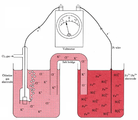
The components of the redox couples at the electrodes in a galvanic cell need not always be a solid and a species in solution. This is evident from Figure \(\PageIndex{2}\). In this case the spontaneous redox reaction
\[\text{2Fe}^{2+}(aq) + \text{Cl}_2(g) \rightarrow \text{2Fe}^{3+}(aq) + \text{2Cl}^{-}(aq)\label{4} \]
is involved. The oxidation half-equation at the anode is
\[\text{Fe}^{3+}(aq) \rightarrow \text{Fe}^{2+}(aq) + e^{-}\label{5} \]
Thus at the right-hand electrode in Figure \(\PageIndex{2}\) both components of the redox couple are in aqueous solution. Reaction \(\ref{5}\) occurs at the surface of the platinum wire, which conducts the released electrons to the external circuit.
The left-hand electrode in Figure \(\PageIndex{2}\) is a gas electrode. It consists of a platinum strip dipping in a solution which contains chloride ions. The electrode is surrounded by a glass tube through which chlorine gas can be pumped. At this electrode the reaction is a reduction:
\[\text{Cl}_2(g) + \text{2}e^{-} \rightarrow \text{2Cl}^{-}(aq)\label{6} \]
Therefore the left-hand electrode is the cathode. Since electrons are forced into the external circuit at the anode and withdrawn at the cathode, electrons flow from right to left in this cell.