
Time Gating
- Page ID
- 76377

\( \newcommand{\vecs}[1]{\overset { \scriptstyle \rightharpoonup} {\mathbf{#1}} } \)
\( \newcommand{\vecd}[1]{\overset{-\!-\!\rightharpoonup}{\vphantom{a}\smash {#1}}} \)
\( \newcommand{\dsum}{\displaystyle\sum\limits} \)
\( \newcommand{\dint}{\displaystyle\int\limits} \)
\( \newcommand{\dlim}{\displaystyle\lim\limits} \)
\( \newcommand{\id}{\mathrm{id}}\) \( \newcommand{\Span}{\mathrm{span}}\)
( \newcommand{\kernel}{\mathrm{null}\,}\) \( \newcommand{\range}{\mathrm{range}\,}\)
\( \newcommand{\RealPart}{\mathrm{Re}}\) \( \newcommand{\ImaginaryPart}{\mathrm{Im}}\)
\( \newcommand{\Argument}{\mathrm{Arg}}\) \( \newcommand{\norm}[1]{\| #1 \|}\)
\( \newcommand{\inner}[2]{\langle #1, #2 \rangle}\)
\( \newcommand{\Span}{\mathrm{span}}\)
\( \newcommand{\id}{\mathrm{id}}\)
\( \newcommand{\Span}{\mathrm{span}}\)
\( \newcommand{\kernel}{\mathrm{null}\,}\)
\( \newcommand{\range}{\mathrm{range}\,}\)
\( \newcommand{\RealPart}{\mathrm{Re}}\)
\( \newcommand{\ImaginaryPart}{\mathrm{Im}}\)
\( \newcommand{\Argument}{\mathrm{Arg}}\)
\( \newcommand{\norm}[1]{\| #1 \|}\)
\( \newcommand{\inner}[2]{\langle #1, #2 \rangle}\)
\( \newcommand{\Span}{\mathrm{span}}\) \( \newcommand{\AA}{\unicode[.8,0]{x212B}}\)
\( \newcommand{\vectorA}[1]{\vec{#1}} % arrow\)
\( \newcommand{\vectorAt}[1]{\vec{\text{#1}}} % arrow\)
\( \newcommand{\vectorB}[1]{\overset { \scriptstyle \rightharpoonup} {\mathbf{#1}} } \)
\( \newcommand{\vectorC}[1]{\textbf{#1}} \)
\( \newcommand{\vectorD}[1]{\overrightarrow{#1}} \)
\( \newcommand{\vectorDt}[1]{\overrightarrow{\text{#1}}} \)
\( \newcommand{\vectE}[1]{\overset{-\!-\!\rightharpoonup}{\vphantom{a}\smash{\mathbf {#1}}}} \)
\( \newcommand{\vecs}[1]{\overset { \scriptstyle \rightharpoonup} {\mathbf{#1}} } \)
\(\newcommand{\longvect}{\overrightarrow}\)
\( \newcommand{\vecd}[1]{\overset{-\!-\!\rightharpoonup}{\vphantom{a}\smash {#1}}} \)
\(\newcommand{\avec}{\mathbf a}\) \(\newcommand{\bvec}{\mathbf b}\) \(\newcommand{\cvec}{\mathbf c}\) \(\newcommand{\dvec}{\mathbf d}\) \(\newcommand{\dtil}{\widetilde{\mathbf d}}\) \(\newcommand{\evec}{\mathbf e}\) \(\newcommand{\fvec}{\mathbf f}\) \(\newcommand{\nvec}{\mathbf n}\) \(\newcommand{\pvec}{\mathbf p}\) \(\newcommand{\qvec}{\mathbf q}\) \(\newcommand{\svec}{\mathbf s}\) \(\newcommand{\tvec}{\mathbf t}\) \(\newcommand{\uvec}{\mathbf u}\) \(\newcommand{\vvec}{\mathbf v}\) \(\newcommand{\wvec}{\mathbf w}\) \(\newcommand{\xvec}{\mathbf x}\) \(\newcommand{\yvec}{\mathbf y}\) \(\newcommand{\zvec}{\mathbf z}\) \(\newcommand{\rvec}{\mathbf r}\) \(\newcommand{\mvec}{\mathbf m}\) \(\newcommand{\zerovec}{\mathbf 0}\) \(\newcommand{\onevec}{\mathbf 1}\) \(\newcommand{\real}{\mathbb R}\) \(\newcommand{\twovec}[2]{\left[\begin{array}{r}#1 \\ #2 \end{array}\right]}\) \(\newcommand{\ctwovec}[2]{\left[\begin{array}{c}#1 \\ #2 \end{array}\right]}\) \(\newcommand{\threevec}[3]{\left[\begin{array}{r}#1 \\ #2 \\ #3 \end{array}\right]}\) \(\newcommand{\cthreevec}[3]{\left[\begin{array}{c}#1 \\ #2 \\ #3 \end{array}\right]}\) \(\newcommand{\fourvec}[4]{\left[\begin{array}{r}#1 \\ #2 \\ #3 \\ #4 \end{array}\right]}\) \(\newcommand{\cfourvec}[4]{\left[\begin{array}{c}#1 \\ #2 \\ #3 \\ #4 \end{array}\right]}\) \(\newcommand{\fivevec}[5]{\left[\begin{array}{r}#1 \\ #2 \\ #3 \\ #4 \\ #5 \\ \end{array}\right]}\) \(\newcommand{\cfivevec}[5]{\left[\begin{array}{c}#1 \\ #2 \\ #3 \\ #4 \\ #5 \\ \end{array}\right]}\) \(\newcommand{\mattwo}[4]{\left[\begin{array}{rr}#1 \amp #2 \\ #3 \amp #4 \\ \end{array}\right]}\) \(\newcommand{\laspan}[1]{\text{Span}\{#1\}}\) \(\newcommand{\bcal}{\cal B}\) \(\newcommand{\ccal}{\cal C}\) \(\newcommand{\scal}{\cal S}\) \(\newcommand{\wcal}{\cal W}\) \(\newcommand{\ecal}{\cal E}\) \(\newcommand{\coords}[2]{\left\{#1\right\}_{#2}}\) \(\newcommand{\gray}[1]{\color{gray}{#1}}\) \(\newcommand{\lgray}[1]{\color{lightgray}{#1}}\) \(\newcommand{\rank}{\operatorname{rank}}\) \(\newcommand{\row}{\text{Row}}\) \(\newcommand{\col}{\text{Col}}\) \(\renewcommand{\row}{\text{Row}}\) \(\newcommand{\nul}{\text{Nul}}\) \(\newcommand{\var}{\text{Var}}\) \(\newcommand{\corr}{\text{corr}}\) \(\newcommand{\len}[1]{\left|#1\right|}\) \(\newcommand{\bbar}{\overline{\bvec}}\) \(\newcommand{\bhat}{\widehat{\bvec}}\) \(\newcommand{\bperp}{\bvec^\perp}\) \(\newcommand{\xhat}{\widehat{\xvec}}\) \(\newcommand{\vhat}{\widehat{\vvec}}\) \(\newcommand{\uhat}{\widehat{\uvec}}\) \(\newcommand{\what}{\widehat{\wvec}}\) \(\newcommand{\Sighat}{\widehat{\Sigma}}\) \(\newcommand{\lt}{<}\) \(\newcommand{\gt}{>}\) \(\newcommand{\amp}{&}\) \(\definecolor{fillinmathshade}{gray}{0.9}\)Signal or Outcome Enhancement Strategies
Some emission methods are inherently time-varying. Laser ablation produces a burst of material that condenses in a matter of microseconds. The emission signal varies from an intense, continuum-burdened flash lasting less than 1 microsecond to progressively weaker, but lower background, line emission over the next few tens of microseconds. Detection that can ignore the initial flash has not only better signal-to-background ratio, but also narrower emission lines and thus reduced interelement effects. Similarly, electric spark sampling produces time-varying signals on the same time scale. Time-gating of detection (ignoring light except when signal/background is high and line width is sufficiently small) is thus advantageous. While the time scale is slower, the signal for graphite furnace atomic absorption also varies over 1-2 s. Ignoring signal during e.g. solvent vaporization and sample ashing, then integrating during the period when analyte vapor is generated, gives enhanced signal and reduced background.
There are three common methods of time gating:
- Time-gated integration of photomultiplier output current
- Gated intensifier with array detector
- Streak camera with array detector
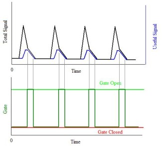
In the first two cases, one ignores light except during a selected window within each event, and averages many such events to get an adequate signal-to-noise ratio. In the adjacent figure, the black line represents emission from, say, repeated laser firings. Within each flash, the blue line represents line emission, useful for elemental analysis, while the remaining light is continuum. Between the grey lines, the ratio of useful emission to background is high and intensity is high enough to improve signal-to-noise. We thus look at photomultiplier current ("open the gate") between the grey lines, ignoring emission at all other times. We thus get high signal-to-background ratio. For information on commercially available electronics, hyperlink here.
One can do the same sort of gated integration with array detectors by inserting an intensifier at the spectrograph focal plane, placing the array immediately behind the intensifier. An example that is well illustrated is linked here. Light ejects photoelectrons just as is the case for a photomultiplier tube. Unlike the photomultiplier, the photocathode is segmented, with each few microns of active surface leading to a resistive pore along which a potential gradient is maintained. Just as with a photomultiplier, electrons impacting on the walls of the tubes set off avalanches, so that one photon eliciting a photoelectron gives rise to an electron avalanche at the distal end of the amplifier tube. The exiting electrons strike a fluorescent screen, replicating the original image at higher intensity. This secondary image is detected. If the potential across the electron multiplying plate is low, no multiplication occurs, and the detector is, effectively, off. Pulsing the potential on has the effect of gating the array detector on. The detector itself is not, in a literal sense, gated, but it responds to incident light only during a gating voltage pulse. This allows boxcar integration for either an x-y scene or for a uniaxially-spatially-resolved spectrum.
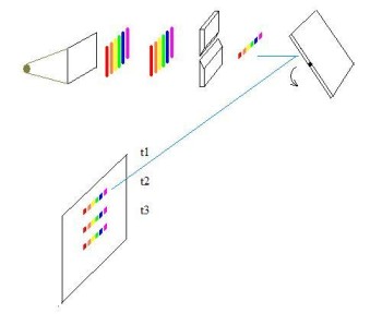
A streak camera, in principle, has the best time resolution of any time gating scheme. A spinning mirror sweeps an image across a photodetector. As shown in the figure, a grating or prism disperses a spectrum, a slit isolates a narrow vertical segment of that spectrum, so that as the mirror spins, the spectrum is displaced along the detector as a function of time. If the event giving rise to the light is synchronized so that the alignment of the mirror and detector is always the same at a given delay after the start of the event, one can see the entire timecourse of the event (at one spatial point), averaged over many repetitions, as a display of intensity as a function of wavelength and time. One simply ignores information at times where signal/background is insufficient. The time resolution is determined by the pixel spacing of the detector, the spinning rate of the mirror, and the distance from mirror to detector.
For a CCD with pixel spacing p, a spinning mirror a distance D from the CCD, and a rotation rate of H Hz, what is the stream camera time resolution? Here's the derivation.