Brayton Cycle
- Page ID
- 1911
\( \newcommand{\vecs}[1]{\overset { \scriptstyle \rightharpoonup} {\mathbf{#1}} } \)
\( \newcommand{\vecd}[1]{\overset{-\!-\!\rightharpoonup}{\vphantom{a}\smash {#1}}} \)
\( \newcommand{\id}{\mathrm{id}}\) \( \newcommand{\Span}{\mathrm{span}}\)
( \newcommand{\kernel}{\mathrm{null}\,}\) \( \newcommand{\range}{\mathrm{range}\,}\)
\( \newcommand{\RealPart}{\mathrm{Re}}\) \( \newcommand{\ImaginaryPart}{\mathrm{Im}}\)
\( \newcommand{\Argument}{\mathrm{Arg}}\) \( \newcommand{\norm}[1]{\| #1 \|}\)
\( \newcommand{\inner}[2]{\langle #1, #2 \rangle}\)
\( \newcommand{\Span}{\mathrm{span}}\)
\( \newcommand{\id}{\mathrm{id}}\)
\( \newcommand{\Span}{\mathrm{span}}\)
\( \newcommand{\kernel}{\mathrm{null}\,}\)
\( \newcommand{\range}{\mathrm{range}\,}\)
\( \newcommand{\RealPart}{\mathrm{Re}}\)
\( \newcommand{\ImaginaryPart}{\mathrm{Im}}\)
\( \newcommand{\Argument}{\mathrm{Arg}}\)
\( \newcommand{\norm}[1]{\| #1 \|}\)
\( \newcommand{\inner}[2]{\langle #1, #2 \rangle}\)
\( \newcommand{\Span}{\mathrm{span}}\) \( \newcommand{\AA}{\unicode[.8,0]{x212B}}\)
\( \newcommand{\vectorA}[1]{\vec{#1}} % arrow\)
\( \newcommand{\vectorAt}[1]{\vec{\text{#1}}} % arrow\)
\( \newcommand{\vectorB}[1]{\overset { \scriptstyle \rightharpoonup} {\mathbf{#1}} } \)
\( \newcommand{\vectorC}[1]{\textbf{#1}} \)
\( \newcommand{\vectorD}[1]{\overrightarrow{#1}} \)
\( \newcommand{\vectorDt}[1]{\overrightarrow{\text{#1}}} \)
\( \newcommand{\vectE}[1]{\overset{-\!-\!\rightharpoonup}{\vphantom{a}\smash{\mathbf {#1}}}} \)
\( \newcommand{\vecs}[1]{\overset { \scriptstyle \rightharpoonup} {\mathbf{#1}} } \)
\( \newcommand{\vecd}[1]{\overset{-\!-\!\rightharpoonup}{\vphantom{a}\smash {#1}}} \)
\(\newcommand{\avec}{\mathbf a}\) \(\newcommand{\bvec}{\mathbf b}\) \(\newcommand{\cvec}{\mathbf c}\) \(\newcommand{\dvec}{\mathbf d}\) \(\newcommand{\dtil}{\widetilde{\mathbf d}}\) \(\newcommand{\evec}{\mathbf e}\) \(\newcommand{\fvec}{\mathbf f}\) \(\newcommand{\nvec}{\mathbf n}\) \(\newcommand{\pvec}{\mathbf p}\) \(\newcommand{\qvec}{\mathbf q}\) \(\newcommand{\svec}{\mathbf s}\) \(\newcommand{\tvec}{\mathbf t}\) \(\newcommand{\uvec}{\mathbf u}\) \(\newcommand{\vvec}{\mathbf v}\) \(\newcommand{\wvec}{\mathbf w}\) \(\newcommand{\xvec}{\mathbf x}\) \(\newcommand{\yvec}{\mathbf y}\) \(\newcommand{\zvec}{\mathbf z}\) \(\newcommand{\rvec}{\mathbf r}\) \(\newcommand{\mvec}{\mathbf m}\) \(\newcommand{\zerovec}{\mathbf 0}\) \(\newcommand{\onevec}{\mathbf 1}\) \(\newcommand{\real}{\mathbb R}\) \(\newcommand{\twovec}[2]{\left[\begin{array}{r}#1 \\ #2 \end{array}\right]}\) \(\newcommand{\ctwovec}[2]{\left[\begin{array}{c}#1 \\ #2 \end{array}\right]}\) \(\newcommand{\threevec}[3]{\left[\begin{array}{r}#1 \\ #2 \\ #3 \end{array}\right]}\) \(\newcommand{\cthreevec}[3]{\left[\begin{array}{c}#1 \\ #2 \\ #3 \end{array}\right]}\) \(\newcommand{\fourvec}[4]{\left[\begin{array}{r}#1 \\ #2 \\ #3 \\ #4 \end{array}\right]}\) \(\newcommand{\cfourvec}[4]{\left[\begin{array}{c}#1 \\ #2 \\ #3 \\ #4 \end{array}\right]}\) \(\newcommand{\fivevec}[5]{\left[\begin{array}{r}#1 \\ #2 \\ #3 \\ #4 \\ #5 \\ \end{array}\right]}\) \(\newcommand{\cfivevec}[5]{\left[\begin{array}{c}#1 \\ #2 \\ #3 \\ #4 \\ #5 \\ \end{array}\right]}\) \(\newcommand{\mattwo}[4]{\left[\begin{array}{rr}#1 \amp #2 \\ #3 \amp #4 \\ \end{array}\right]}\) \(\newcommand{\laspan}[1]{\text{Span}\{#1\}}\) \(\newcommand{\bcal}{\cal B}\) \(\newcommand{\ccal}{\cal C}\) \(\newcommand{\scal}{\cal S}\) \(\newcommand{\wcal}{\cal W}\) \(\newcommand{\ecal}{\cal E}\) \(\newcommand{\coords}[2]{\left\{#1\right\}_{#2}}\) \(\newcommand{\gray}[1]{\color{gray}{#1}}\) \(\newcommand{\lgray}[1]{\color{lightgray}{#1}}\) \(\newcommand{\rank}{\operatorname{rank}}\) \(\newcommand{\row}{\text{Row}}\) \(\newcommand{\col}{\text{Col}}\) \(\renewcommand{\row}{\text{Row}}\) \(\newcommand{\nul}{\text{Nul}}\) \(\newcommand{\var}{\text{Var}}\) \(\newcommand{\corr}{\text{corr}}\) \(\newcommand{\len}[1]{\left|#1\right|}\) \(\newcommand{\bbar}{\overline{\bvec}}\) \(\newcommand{\bhat}{\widehat{\bvec}}\) \(\newcommand{\bperp}{\bvec^\perp}\) \(\newcommand{\xhat}{\widehat{\xvec}}\) \(\newcommand{\vhat}{\widehat{\vvec}}\) \(\newcommand{\uhat}{\widehat{\uvec}}\) \(\newcommand{\what}{\widehat{\wvec}}\) \(\newcommand{\Sighat}{\widehat{\Sigma}}\) \(\newcommand{\lt}{<}\) \(\newcommand{\gt}{>}\) \(\newcommand{\amp}{&}\) \(\definecolor{fillinmathshade}{gray}{0.9}\)The Brayton Cycle is a thermodynamic cycle that describes how gas turbines operate. The idea behind the Brayton Cycle is to extract energy from flowing air and fuel to generate usuable work which can be used to power many vehicles by giving them thrust. The most basic steps in extracting energy is compression of flowing air, combustion, and then expansion of that air to create work and also power the compression at the same time. The usefulness of the Brayton Cycle is tremendous due to the fact it is the backbone in driving many vehicles such as jets, helicopters, and even submarines.
Introduction
The first gas turbine that implemented the Brayton Cycle (not knowingly however, because it was created before the Brayton Cycle was even established) was John Barber's gas turbine patented in 1791. The idea of the machine was to compress atmospheric air in one chamber and fuel in another chamber and both chambers would be connected to a combustion vessel. Once the air has mixed with the fuel and reacted, the energy from the combustion would be used to spin a turbine to do useful work. However, because back in the late 18th century there was lack of technological advances and such, the gas turbine did not have enough energy to pressurize the gases and do useful work at the same time therefore it was not used.
George Brayton was an engineer that designed the first continuous ignition combustion engine which was a two-stroke engine that was sold under the name "Brayton's Ready Motors." The design employed the thermodynamic processes that is now considered "The Brayton Cycle," but is also coined The Joule Cycle. The gas turbine was patented in 1872. The design was a engine connected to a reservoir of pressurized atmospheric air and gas which would only turn on if a valve was turned. This would release the pressurized gas to a combustion vessel, which would turn pistons to create mechanical work and re-compress the gas in the reservoir.
John Barber's Gas Turbine (1791)
The Brayton Cycle for John barber's gas turbine is incomplete due to the fact energy is not redirected into compression of the initial gases, yet because this was one of the first prominent gas turbine engines ever created, it still holds much significance. Fuel and atmospheric gas is held in different chambers and heated to increase pressure. This is in part to the ideal gas law PV = nRT, and since the volume of the vessel stays constant, an increase in temperature increases pressure. The gas combine into a square compartment where a spark or flame ignites the mixture which then rapidly increases temperature (but not pressure because the gas quickly escapes to spin the turbine).
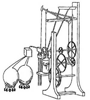
Although this is a very crude gas turbine engine, it nontheless was a great foundations for further scientific advancements and the development of the Brayton Cycle.
George Brayton's Gas Turbine (1872)
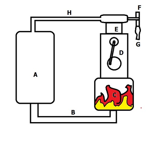
George Brayton's gas turbine was the first and most prominent fully operational gas turbine that implemented the Brayton Cycle. Gas is pressurized and held in reservoir A, where a valve would release it to move through tunnel B and be ignited in chamber C. This is an isobaric process due to the fact any increase in pressure would just push the gas out of the engine. When work is done on the D piston, mechanical work can be employed for a variety of things, such as generation of electricity or movement, and there is also a piston in compartment E that sucks in atmospheric air from valve F. Valve G is a fitting to a fuel cell where the fuel to air ratio can be set so that a desired ratio for maximum efficiency is kept. The gas is then mechanically compressed back into reservoir A through an adiabatic process due to the piston E.
Modern Day Jet Gas Turbine
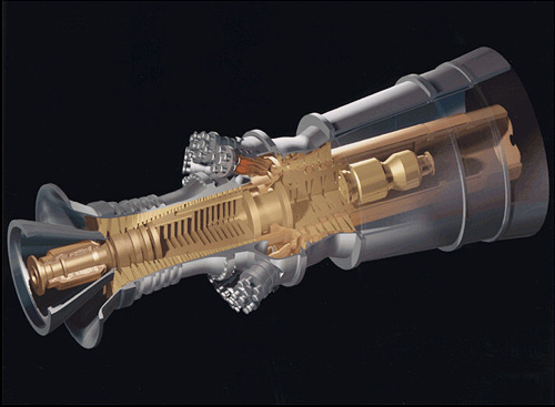
This is one of the many modern day gas turbine engines that utilize the Brayton Cycle in order to power many vehicles or generate power. At the front of the engine is the inlet of the compression chamber so that air is sucked in by the many turbines that are constantly spinning and angled in a specific location for optimum air compression. Enough the air is compressed enough in the middle of the engine (the combustion vessel), fuel is added to the combustion chamber and an ignition is initiated, where the extremely exothermic reaction causes the gas to violently exits the engine in the expansion chamber in the back of the engine. There are turbines right in front of the expansion chamber that is connected to the turbins in the compression chamber so the whole engine is a continuous cycle as long as there is a steady stream of fuel being introduced into the combustion chamber.
Ideal Brayton Cycle
A quick qualitative look at how the Brayton Cycle works it by reviewing how a jet engine works. A gas turbine from a jet's wing sucks in atmospheric air from the back of its engine and is compressed in the mixing/combustion chamber. In the mixing/combustion chamber, fuel is mixed with the compressed atmospheric air, where it is ignited and left to exit in the expansion chamber. The energy that comes out of the back of the gas turbine is work used to power the compression step as well as give thrust to the jet.
The Brayton Cycle can then be described quantitatively in the gas turbine engine of a jet by two diagrams, the Temperature/Entropy Diagram and the Pressure/Volume Diagram.
Temperature/Entropy Diagram
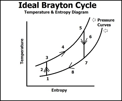
In this diagram, we see that there are 8 processses to describe the Brayton cycle in terms of temperature, entropy, and pressure.
(1) Ambiant air in the atmosphere that is currently undisturbed.
(1 -> 2) Ambiant air comes into contact with the compressor of the gas turbine and the pressure and temperature rises dramatically. The rise in pressure comes from work being done the air by the compressor which packs the air into the mixer/combustion chamber, and the rise in pressure causes a rise in temperature in the gas molecules because volume of the vessel stays constant (PV = nRT). Because this is an ideal process, entropy is believed to stay the same, thus this is an isentropic process (in reality though, entropy does increase due to the flow and movement of the gas molecules).
(3 -> 5) The atmospheric air has been compacted into the combustion chamber where gaseous fuel is mixed with the air. Once this mixture has been ignited, we a see a steep rise in the temperature and entropy (not the pressure, because the curves represent a specific value of pressure, so this is an isobaric process) due to the combustion reaction of the fuel and air. The energy from the chemical bonds in the fuel are broken due to ignition and a highly exothermic reaction occurs which raises entropy because of the breaking down of hydrocarbon chains to water and air (more molecules) and raises the temperature due to increased ambiant energy from the exothermic reaction.
(5 -> 8) At point 5, the pressurized fuel and air leave the combustion chamber to the expansion chamber, where we see a quick drop in pressure due to a larger volume and exposure to the surroundings. The energy from the combustion chamber is used two for two purposes: spinning a turbine that is connected to the compressor (which keeps the Brayton Cycle running continuously) and as thrust. These two purposes represent point 6 and ideally is an isentropic process. The quick drop in pressure shows how the energy from the air in the combustion energy is used mechanically to turn a turbine that will run the compressor process because the energy it takes to compress the atmospheric energy is lesser than the energy produced from the ignition of the fuel. The energy left over from spinning the turbine is the used as thrust to do work (such as flight in a jet). The expelled air then becomes ambiant air that is of a higher energy level than the air from point 1, but will eventually lose energy to the surroundings (isobaric process) and become the initial ambiant air.
Pressure/Volume Diagram
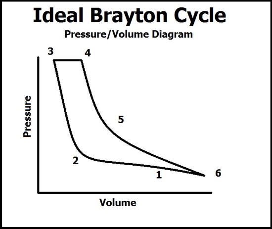
In this diagram, there are six processes that describe the pressure and volume of the gas. A common mistake is by thinking the volume relates to the vessel of the reaction, when in fact it is the volume of the gas. This graph coincides with the TS diagram but do not progress through the points at the same time (because this diagram only has 6 points).
(1 -> 3) The ambiant air is sucked into the compressor where the volume of the gas quickly falls due to the compression into the combustion chamber. As compression continues, the pressure of the gas begins to quickly rise at point 2 after the volume of the combustion chamber is filled and peaks at point 3. At point 3, ignition occurs.
(4 -> 6) As ignition occurs, the pressure of the gas remains constant due to the face the gas is able to escape into the expansion chamber (notice that even though gas is leaving, the compression process is still working, so any pressure lost from the gas leaving is held constant from the gas entering the combustion chamber) which results in a rise in volume of the energized gas. As the gas leaves into the atmosphere, the pressure drops and the volume of the gas expands to what it was in point 1. Work is done from the expansion of the gas which pushes out of the expansion chamber with high force. This force is then used to spin turbins and give thrust.
Non-Ideal/Realistic Processes of the Brayton Cycle
The ideal processes shown in the above diagrams are used to study and understand the Brayton Cycle better. However, some corrections are needed when applied to real world problems. The first problem is the fact that in the compression process, it is believed to be isentropic. This is wrong, because the high speed flow of the ambiant air increases the entropy (higher energy molecules) and thus is not an isentropic process. It is actually an adiabatic process because no heat exchange occurs in the gas and only mechanical work is done for compression. This also relates back to the expansion process where the gas expands in the expansion chamber but has yet to leave into the atmosphere. Ideally it is isentropic, but the expansion of gas does increase entropy, therefore it is actually an adiabatic process because again, there is not heat exchange (only mechanical work done by expansion).
The non-ideal processes of the Brayton Cycle points out a problem; that the work used to raise entropy is thus a leak in the amount of work that could have been used for useful mechanical energy. A set of equations is then used to calculate the efficiency of the Brayton Cycle at certain pressures and temperatures.
Efficiency of the Brayton Cycle
To find the efficiency of the Brayton Cycle, we must find out how much work each process contributes to the total internal energy. We will be analyzing the PV diagram above to do this.
First, the internal energy
\[U = q_1 + q_2 - w = 0\]
is equal to zero because the first law of thermodynamics states that energy is not destroyed or created, and because in the Brayton cycle the final state function of the gas is the initial, U = 0.
This means
\[w = q_1 + q_2\]
where \(q_1\) is the heat recieved by the combustion (so it is negative) and \(q_2\) is the heat released after expansion.
If you treat the gas as a perfect gas with constant specific heats, we can find the heat addition from the combuster to be
\[q_1 = c_p(T_I - T_F)\]
and the heat lost to the atmosphere
\[q_2 = c_p(T_F - T_I)\]
Where \(T_F\) is the final temperature of the combustion or "heat lost to the atmosphere" part and the latter is the initial. (So in the PV curve, the combustion process would have \(q_1 = c_p(T_4 - T_3)\)
So now we have expressed the amount of heat lost and gained in terms of temperatures, we can re-establish the equation to find eta (thermal efficiency)
\[\eta = \dfrac{\textrm{Net work}}{\textrm{Heat in}} = \dfrac{c_p[(T_c -T_c) - (T_d - T_a)]}{c_p(T_[T_c = T_b]} = 1 - \frac{(T_d-T_a)}{(T_c-T_b)} = 1 - \frac{T_a(T_d/T_a-1)}{T_b(T_c/T_b-1)}.\]
where c is the final temperature of the combustion process and b is the initial temperature before combustion and a is the initial temperature of the undisturbed gas and d is the temperature of the gas after it has be expelled. The corresponding numbers to letters from the PV graph is a = 2; b = 3; c = 4; d = 6.
The smaller the temperature ratio is the higher the efficiency of the Braytons cycle is. So that is, the more heat input into the system and the smaller amount of heat lost to the atmosphere will significantly reduce the temperature ratio and have a higher percentage of efficiency.
References
- Hünecke, Klaus. Jet Engines: Fundamentals of Theory, Design, and Operation. Osceola, WI, USA: Motor International, 1997. Print.
- Jackson, W. D., G. A. Brown, J. L. Kerrebrock, and R. E. Stickney. Research on New Concepts in Energy Conversion. Ft. Belvoir: Defense Technical Information Center, 1965. Print.
- Shaw, John E. "Comparing Carnot, Stirling, Otto, Brayton, and Diesel Cycles"Transactions of the Missouri Academy of Science (2008): 1-6. Print.
Outside Links
- http://www.nndb.com/people/236/000175708/
- www.if.uidaho.edu/~gunner/Tur...TRODUCTION.pdf
- www.google.com/patents?id=vWl...page&q&f=false
- http://www.grc.nasa.gov/WWW/K-12/air...e/brayton.html
- http://web.mit.edu/16.unified/www/SP...es/node27.html
Problems
- There are four processes in the ideal and non-ideal Brayton Cycle. List them (both ideal and non - ideal) in the correct order and briefly say what is happening (regarding to a jet engine gas turbine).
- During the combustion phase of the Brayton Cycle, mark what happens to the following conditions:
| Increase | Decrease | Constant | |
| Entropy (ideal (mark x)/non-ideal (mark o)) | |||
| Temperature | |||
| Volume | |||
| Pressure |
- During the combustion phase of the Brayton Cycle, the temperature before ignition was 300 K. After ignition, the temperature of the gaseous mixture was 4000 K. Assume the heat absorbed from the atmosphere to be 5000 K. Find the efficiency of that gas turbine.
- From the data in question 3, find \(q_1\) and \(q_2\) assuming \(c_p= 5\).
- Why does entropy stay constant (what reasoning) in the ideal Brayton Cycle but changes in the non-ideal Brayton Cycle.
Solutions
1. Ideal
- Isentropic - Entropy stays as compression occurs.
- Isobaric - Pressure constant as combustion occurs to where heat is evolved.
- Isentropic - Entropy stays as expansion occurs.
- Isobaric - Pressure constant as heat from reaction goes into the atmosphere.
Non-Ideal
- Adiabatic - Compression (no heat exchange).
- Isobaric - Same as ideal.
- Adiabatic - Expansion (no heat exchange).
- Isobaric - Same as ideal.
2.
| Increase | Decrease | Constant | |
| Entropy (ideal (mark x)/non-ideal (mark o)) | xo (+ energy = + entropy) | ||
| Temperature | x (exothermic) | ||
| Volume | x (expansion) | ||
| Pressure | x (isobaric; gas escapes before pressure +) |
3. \(1 - (4000 - 300)/5000 = 0.26\). Which means it is running at 26% efficiency.
4. ANS for combustion phase = 5(300 - 4000) = -18500
\(q_2\) cannot be found because the initial temperature of the air was not given, therefore no solution.
5. Ideally, compression or expansion does not cause entropy (disorder in the system) to change because nothing is causing the the molecules to increase in energy was they are being pushed together or going apart, thus entropy stays constant. However, in the real world, the mechanical energy pushing the molecules together (the compression turbine) causes them to gain molecular energy and does increase entropy in the system.
Contributors and Attributions
- Khoa Nguyen


