
1: Introduction to 3D Printing
- Page ID
- 474466
\( \newcommand{\vecs}[1]{\overset { \scriptstyle \rightharpoonup} {\mathbf{#1}} } \)
\( \newcommand{\vecd}[1]{\overset{-\!-\!\rightharpoonup}{\vphantom{a}\smash {#1}}} \)
\( \newcommand{\dsum}{\displaystyle\sum\limits} \)
\( \newcommand{\dint}{\displaystyle\int\limits} \)
\( \newcommand{\dlim}{\displaystyle\lim\limits} \)
\( \newcommand{\id}{\mathrm{id}}\) \( \newcommand{\Span}{\mathrm{span}}\)
( \newcommand{\kernel}{\mathrm{null}\,}\) \( \newcommand{\range}{\mathrm{range}\,}\)
\( \newcommand{\RealPart}{\mathrm{Re}}\) \( \newcommand{\ImaginaryPart}{\mathrm{Im}}\)
\( \newcommand{\Argument}{\mathrm{Arg}}\) \( \newcommand{\norm}[1]{\| #1 \|}\)
\( \newcommand{\inner}[2]{\langle #1, #2 \rangle}\)
\( \newcommand{\Span}{\mathrm{span}}\)
\( \newcommand{\id}{\mathrm{id}}\)
\( \newcommand{\Span}{\mathrm{span}}\)
\( \newcommand{\kernel}{\mathrm{null}\,}\)
\( \newcommand{\range}{\mathrm{range}\,}\)
\( \newcommand{\RealPart}{\mathrm{Re}}\)
\( \newcommand{\ImaginaryPart}{\mathrm{Im}}\)
\( \newcommand{\Argument}{\mathrm{Arg}}\)
\( \newcommand{\norm}[1]{\| #1 \|}\)
\( \newcommand{\inner}[2]{\langle #1, #2 \rangle}\)
\( \newcommand{\Span}{\mathrm{span}}\) \( \newcommand{\AA}{\unicode[.8,0]{x212B}}\)
\( \newcommand{\vectorA}[1]{\vec{#1}} % arrow\)
\( \newcommand{\vectorAt}[1]{\vec{\text{#1}}} % arrow\)
\( \newcommand{\vectorB}[1]{\overset { \scriptstyle \rightharpoonup} {\mathbf{#1}} } \)
\( \newcommand{\vectorC}[1]{\textbf{#1}} \)
\( \newcommand{\vectorD}[1]{\overrightarrow{#1}} \)
\( \newcommand{\vectorDt}[1]{\overrightarrow{\text{#1}}} \)
\( \newcommand{\vectE}[1]{\overset{-\!-\!\rightharpoonup}{\vphantom{a}\smash{\mathbf {#1}}}} \)
\( \newcommand{\vecs}[1]{\overset { \scriptstyle \rightharpoonup} {\mathbf{#1}} } \)
\(\newcommand{\longvect}{\overrightarrow}\)
\( \newcommand{\vecd}[1]{\overset{-\!-\!\rightharpoonup}{\vphantom{a}\smash {#1}}} \)
\(\newcommand{\avec}{\mathbf a}\) \(\newcommand{\bvec}{\mathbf b}\) \(\newcommand{\cvec}{\mathbf c}\) \(\newcommand{\dvec}{\mathbf d}\) \(\newcommand{\dtil}{\widetilde{\mathbf d}}\) \(\newcommand{\evec}{\mathbf e}\) \(\newcommand{\fvec}{\mathbf f}\) \(\newcommand{\nvec}{\mathbf n}\) \(\newcommand{\pvec}{\mathbf p}\) \(\newcommand{\qvec}{\mathbf q}\) \(\newcommand{\svec}{\mathbf s}\) \(\newcommand{\tvec}{\mathbf t}\) \(\newcommand{\uvec}{\mathbf u}\) \(\newcommand{\vvec}{\mathbf v}\) \(\newcommand{\wvec}{\mathbf w}\) \(\newcommand{\xvec}{\mathbf x}\) \(\newcommand{\yvec}{\mathbf y}\) \(\newcommand{\zvec}{\mathbf z}\) \(\newcommand{\rvec}{\mathbf r}\) \(\newcommand{\mvec}{\mathbf m}\) \(\newcommand{\zerovec}{\mathbf 0}\) \(\newcommand{\onevec}{\mathbf 1}\) \(\newcommand{\real}{\mathbb R}\) \(\newcommand{\twovec}[2]{\left[\begin{array}{r}#1 \\ #2 \end{array}\right]}\) \(\newcommand{\ctwovec}[2]{\left[\begin{array}{c}#1 \\ #2 \end{array}\right]}\) \(\newcommand{\threevec}[3]{\left[\begin{array}{r}#1 \\ #2 \\ #3 \end{array}\right]}\) \(\newcommand{\cthreevec}[3]{\left[\begin{array}{c}#1 \\ #2 \\ #3 \end{array}\right]}\) \(\newcommand{\fourvec}[4]{\left[\begin{array}{r}#1 \\ #2 \\ #3 \\ #4 \end{array}\right]}\) \(\newcommand{\cfourvec}[4]{\left[\begin{array}{c}#1 \\ #2 \\ #3 \\ #4 \end{array}\right]}\) \(\newcommand{\fivevec}[5]{\left[\begin{array}{r}#1 \\ #2 \\ #3 \\ #4 \\ #5 \\ \end{array}\right]}\) \(\newcommand{\cfivevec}[5]{\left[\begin{array}{c}#1 \\ #2 \\ #3 \\ #4 \\ #5 \\ \end{array}\right]}\) \(\newcommand{\mattwo}[4]{\left[\begin{array}{rr}#1 \amp #2 \\ #3 \amp #4 \\ \end{array}\right]}\) \(\newcommand{\laspan}[1]{\text{Span}\{#1\}}\) \(\newcommand{\bcal}{\cal B}\) \(\newcommand{\ccal}{\cal C}\) \(\newcommand{\scal}{\cal S}\) \(\newcommand{\wcal}{\cal W}\) \(\newcommand{\ecal}{\cal E}\) \(\newcommand{\coords}[2]{\left\{#1\right\}_{#2}}\) \(\newcommand{\gray}[1]{\color{gray}{#1}}\) \(\newcommand{\lgray}[1]{\color{lightgray}{#1}}\) \(\newcommand{\rank}{\operatorname{rank}}\) \(\newcommand{\row}{\text{Row}}\) \(\newcommand{\col}{\text{Col}}\) \(\renewcommand{\row}{\text{Row}}\) \(\newcommand{\nul}{\text{Nul}}\) \(\newcommand{\var}{\text{Var}}\) \(\newcommand{\corr}{\text{corr}}\) \(\newcommand{\len}[1]{\left|#1\right|}\) \(\newcommand{\bbar}{\overline{\bvec}}\) \(\newcommand{\bhat}{\widehat{\bvec}}\) \(\newcommand{\bperp}{\bvec^\perp}\) \(\newcommand{\xhat}{\widehat{\xvec}}\) \(\newcommand{\vhat}{\widehat{\vvec}}\) \(\newcommand{\uhat}{\widehat{\uvec}}\) \(\newcommand{\what}{\widehat{\wvec}}\) \(\newcommand{\Sighat}{\widehat{\Sigma}}\) \(\newcommand{\lt}{<}\) \(\newcommand{\gt}{>}\) \(\newcommand{\amp}{&}\) \(\definecolor{fillinmathshade}{gray}{0.9}\)In this class you have created two printed circuit boards, one for a RGB LED and one for a DHT22 Temperature and Humidity board. If you look at the bottom of these boards you will see the wire traces and your solder mounts, and you want to protect these and keep them from being shorted. So you will make measurements of the size of the board and then make a container to place them in with a 3D printer. Your design also needs to have an offset, so the board "floats" in the container. So in this class we will learn how to use 3D printers to house our sensors and other devices we create.
3D printing is essentially a computer output operation where commands are given to a 3D printer to create an object. There are multiple types of 3D printing and we will look at plastic extrusion processes where filament in a plastic wire is heated in a nozzle and horizontally extruded onto a platform that is built up layer after layer. As such this is called an additive manufacturing process.

3D Development Process
We will look at making 3D objects as a development process. First is to generate a CAD file with CAD software that represents a 3D model of the object you want. We will see there are many types of CAD files and many of these are unique to certain software programs. There is a common CAD file for making 3D images that can be read by almost all CAD software and these are STL files, so the first step is to build the object using the intrinsic CAD file of the software we are using, and then convert it to a STL file. Now we need to convert the STL file to something the 3D printer can use and this is called slicing, where we make slices along the vertical access. The software that does this needs to interact with the printer as different printers have different features. A common file format is the Gcode format and that is the format we will use in this class. In making the Gcode file we need to identify what type of plastic we are using, how fast the nozzle moves, things like the bed temperature, nozzle temperature, extruder height, etc.. Figure \(\PageIndex{2}\) illustrates these steps in going from creating the file to generating the 3D object.
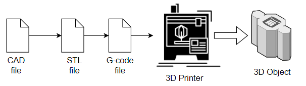 Figure \(\PageIndex{2}\): Copy and Paste Caption heFlow chart for process of making 3D objects. (Belford, cc-by)
CAD Files
CAD stands for Computer Aided Design and there are many types of CAD software and many application of CAD software. There are many options for CAD software and there are multiple CAD file types, many of which are interchangable. What is important is that you can export your file as a STL file, which most printer software can convert to a file that the printer can read. If you want to design your own object you need to start with some CAD software, but if you want to make a common object, it may be easier to look at some online repositories of STL files, and simply convert those to code that your printer can read. CAD software can get very complicated and very expensive and there are three CAD software programs we will consider in this class.
- Autodesk Tinkercad (section 1.9.4) - this is actually a very easy to use free web interface and is a suggested starting point if you are new to CAD
- Autodesk Fusion (section 1.9.5) - this is free to active students and a fairly advanced CAD software. If you are real serious and wish to become professionally involved with uses CAD software then you may even want to go to the Autodesktop professional. As a student you have access to a huge number of Autodesk programs and you should check out their site.
- FreeCAD (section 1.9.6) - This is an open source CAD software with a lot of features, which as a hobbiest, you can continue to use after the course is over (and you are no longer a student).
It should be noted that CAD is not a file type, and there are many CAD file types, depending on the CAD software. There are also sort of two types of CAD software programs, programmatic ones that use scripts of code to generate the image, and GUI ones, that use a graphical user interface to generate the image.
STL Files
STL stands for Sterolithography although there are numerous backronyms like "Standard Triangle Language" and "Standard Tessellation Language". These are essentially polygonal structures based on the Cartesian coordinate system. If you consider the XY plan as the horizontal plan and the z axis as the vertical, then the *.STL file can be sliced along the z axis into layers that the 3D nozzle can use to make a path for extruding the plastic along the XY plan, one layer at a time, as it moves up the z axis. The important thing is that the CAD file be exported to a STL file as that file can be converted to a file that your printer can use, which is typically a G-code file. The STL file essentially contains the geometric data of the object and is a standard file type in the sense that most CAD software programs can generate an STL file.
G-code
The G in G-code stands for geometry and this is the file that the software uses to control automated machines like a 3D printers. This file is used in many types of computer-aided manufacturing abd there are many variants of G-code. In 3D printing the actual file is specific to the 3D printer machinery that you are using. For example, does your printer of one or two nozzles? Does the bed rise along the vertical axis or does the nozzle? This file also specifies parameters such as the nozzle and bed temperatures, which you specify based on the type of plastic you are using. You create the G-code file when you slice the STL file, where each slice along the vertical (Z) axis contains the instructions for the nozzle to extrude the plastic along the horizontal (XY) plane. So the first thing you need to do is find software that can generate G-code that can be read by the microcontrollers on your 3D printer. If the 3D printer manufacturer does not provide an appropriate slicer you could try a resource like PrusaSlicer or Ultimaker Cura.