Chemistry LibreTexts

9.12: Amorphous Semiconductors

  • Page ID
    226711
  • \( \newcommand{\vecs}[1]{\overset { \scriptstyle \rightharpoonup} {\mathbf{#1}} } \)

    \( \newcommand{\vecd}[1]{\overset{-\!-\!\rightharpoonup}{\vphantom{a}\smash {#1}}} \)

    \( \newcommand{\id}{\mathrm{id}}\) \( \newcommand{\Span}{\mathrm{span}}\)

    ( \newcommand{\kernel}{\mathrm{null}\,}\) \( \newcommand{\range}{\mathrm{range}\,}\)

    \( \newcommand{\RealPart}{\mathrm{Re}}\) \( \newcommand{\ImaginaryPart}{\mathrm{Im}}\)

    \( \newcommand{\Argument}{\mathrm{Arg}}\) \( \newcommand{\norm}[1]{\| #1 \|}\)

    \( \newcommand{\inner}[2]{\langle #1, #2 \rangle}\)

    \( \newcommand{\Span}{\mathrm{span}}\)

    \( \newcommand{\id}{\mathrm{id}}\)

    \( \newcommand{\Span}{\mathrm{span}}\)

    \( \newcommand{\kernel}{\mathrm{null}\,}\)

    \( \newcommand{\range}{\mathrm{range}\,}\)

    \( \newcommand{\RealPart}{\mathrm{Re}}\)

    \( \newcommand{\ImaginaryPart}{\mathrm{Im}}\)

    \( \newcommand{\Argument}{\mathrm{Arg}}\)

    \( \newcommand{\norm}[1]{\| #1 \|}\)

    \( \newcommand{\inner}[2]{\langle #1, #2 \rangle}\)

    \( \newcommand{\Span}{\mathrm{span}}\) \( \newcommand{\AA}{\unicode[.8,0]{x212B}}\)

    \( \newcommand{\vectorA}[1]{\vec{#1}}      % arrow\)

    \( \newcommand{\vectorAt}[1]{\vec{\text{#1}}}      % arrow\)

    \( \newcommand{\vectorB}[1]{\overset { \scriptstyle \rightharpoonup} {\mathbf{#1}} } \)

    \( \newcommand{\vectorC}[1]{\textbf{#1}} \)

    \( \newcommand{\vectorD}[1]{\overrightarrow{#1}} \)

    \( \newcommand{\vectorDt}[1]{\overrightarrow{\text{#1}}} \)

    \( \newcommand{\vectE}[1]{\overset{-\!-\!\rightharpoonup}{\vphantom{a}\smash{\mathbf {#1}}}} \)

    \( \newcommand{\vecs}[1]{\overset { \scriptstyle \rightharpoonup} {\mathbf{#1}} } \)

    \( \newcommand{\vecd}[1]{\overset{-\!-\!\rightharpoonup}{\vphantom{a}\smash {#1}}} \)

    \(\newcommand{\avec}{\mathbf a}\) \(\newcommand{\bvec}{\mathbf b}\) \(\newcommand{\cvec}{\mathbf c}\) \(\newcommand{\dvec}{\mathbf d}\) \(\newcommand{\dtil}{\widetilde{\mathbf d}}\) \(\newcommand{\evec}{\mathbf e}\) \(\newcommand{\fvec}{\mathbf f}\) \(\newcommand{\nvec}{\mathbf n}\) \(\newcommand{\pvec}{\mathbf p}\) \(\newcommand{\qvec}{\mathbf q}\) \(\newcommand{\svec}{\mathbf s}\) \(\newcommand{\tvec}{\mathbf t}\) \(\newcommand{\uvec}{\mathbf u}\) \(\newcommand{\vvec}{\mathbf v}\) \(\newcommand{\wvec}{\mathbf w}\) \(\newcommand{\xvec}{\mathbf x}\) \(\newcommand{\yvec}{\mathbf y}\) \(\newcommand{\zvec}{\mathbf z}\) \(\newcommand{\rvec}{\mathbf r}\) \(\newcommand{\mvec}{\mathbf m}\) \(\newcommand{\zerovec}{\mathbf 0}\) \(\newcommand{\onevec}{\mathbf 1}\) \(\newcommand{\real}{\mathbb R}\) \(\newcommand{\twovec}[2]{\left[\begin{array}{r}#1 \\ #2 \end{array}\right]}\) \(\newcommand{\ctwovec}[2]{\left[\begin{array}{c}#1 \\ #2 \end{array}\right]}\) \(\newcommand{\threevec}[3]{\left[\begin{array}{r}#1 \\ #2 \\ #3 \end{array}\right]}\) \(\newcommand{\cthreevec}[3]{\left[\begin{array}{c}#1 \\ #2 \\ #3 \end{array}\right]}\) \(\newcommand{\fourvec}[4]{\left[\begin{array}{r}#1 \\ #2 \\ #3 \\ #4 \end{array}\right]}\) \(\newcommand{\cfourvec}[4]{\left[\begin{array}{c}#1 \\ #2 \\ #3 \\ #4 \end{array}\right]}\) \(\newcommand{\fivevec}[5]{\left[\begin{array}{r}#1 \\ #2 \\ #3 \\ #4 \\ #5 \\ \end{array}\right]}\) \(\newcommand{\cfivevec}[5]{\left[\begin{array}{c}#1 \\ #2 \\ #3 \\ #4 \\ #5 \\ \end{array}\right]}\) \(\newcommand{\mattwo}[4]{\left[\begin{array}{rr}#1 \amp #2 \\ #3 \amp #4 \\ \end{array}\right]}\) \(\newcommand{\laspan}[1]{\text{Span}\{#1\}}\) \(\newcommand{\bcal}{\cal B}\) \(\newcommand{\ccal}{\cal C}\) \(\newcommand{\scal}{\cal S}\) \(\newcommand{\wcal}{\cal W}\) \(\newcommand{\ecal}{\cal E}\) \(\newcommand{\coords}[2]{\left\{#1\right\}_{#2}}\) \(\newcommand{\gray}[1]{\color{gray}{#1}}\) \(\newcommand{\lgray}[1]{\color{lightgray}{#1}}\) \(\newcommand{\rank}{\operatorname{rank}}\) \(\newcommand{\row}{\text{Row}}\) \(\newcommand{\col}{\text{Col}}\) \(\renewcommand{\row}{\text{Row}}\) \(\newcommand{\nul}{\text{Nul}}\) \(\newcommand{\var}{\text{Var}}\) \(\newcommand{\corr}{\text{corr}}\) \(\newcommand{\len}[1]{\left|#1\right|}\) \(\newcommand{\bbar}{\overline{\bvec}}\) \(\newcommand{\bhat}{\widehat{\bvec}}\) \(\newcommand{\bperp}{\bvec^\perp}\) \(\newcommand{\xhat}{\widehat{\xvec}}\) \(\newcommand{\vhat}{\widehat{\vvec}}\) \(\newcommand{\uhat}{\widehat{\uvec}}\) \(\newcommand{\what}{\widehat{\wvec}}\) \(\newcommand{\Sighat}{\widehat{\Sigma}}\) \(\newcommand{\lt}{<}\) \(\newcommand{\gt}{>}\) \(\newcommand{\amp}{&}\) \(\definecolor{fillinmathshade}{gray}{0.9}\)

    Amorphous semiconductors are disordered or glassy forms of crystalline semiconductor materials. Like non-conducting glasses, they are network structures with primarily covalent bonding. Crystalline silicon, which has the diamond structure, is an ordered arrangement of fused six-membered silicon rings, all in the "chair" conformation, as we saw in Ch. 8. The local bonding environment of the silicon atoms is tetrahedral. The silicon atoms in amorphous silicon (a-Si) are also predominantly tetrahedrally coordinated, but there is no long-range order in the structure. In addition to six-membered rings, there are five- and seven-membered rings, as well as some "dangling bond" sites in which Si atoms have only three nearest neighbors.

    clipboard_eb1e2af117b2cd05ec9f220b8814c17f7.png

    Schematic illustration of the structures of crystalline silicon (left), amorphous silicon (middle), and amorphous hydrogenated silicon (right)

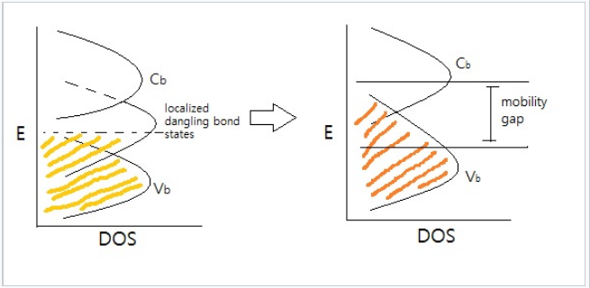
    Two of the most widely studied amorphous semiconductors are a-Si and amorphous selenium, a-Se. Si and Se can both be made in glassy form, usually by sputtering or evaporation at relatively low temperature. In a-Se, as in a-Si, locally, most of the atoms have their "normal" valence, but there are many defects and irregularities in the structure. Dangling bonds in amorphous semiconductors have orbital energies in the middle of gap, and electrons in these states are effectively non-bonding. Because these dangling bond sites are far apart from each other, there is little orbital overlap between them, and they also exist over a range of energies. Electrons in these mid-gap states are therefore localized, a phenomenon known as Anderson localizaton. Amorphous Si is insulating because electrons the Fermi level (in the middle of the gap) are not mobile in the lattice. These localized states create a mobility gap, and only electrons in states that are strongly bonding or antibonding are delocalized. Therefore, unmodified a-Si is not very useful as a semiconductor. However, by hydrogenating the material as it is formed (typically in a plasma of H atoms), the under-coordinated Si atoms are bonded to hydrogen atoms. This generates filled bonding and empty antibonding orbitals, the energies of which are outside the mobility gap. Hydrogenation thus lowers the density of states in the mobility gap. Hydrogenated amorphous silicon (a-Si:H) is insulating in the dark, but is a good photoconductor because light absorption creates electrons and holes in mobile states that are outside the mobility gap.

    clipboard_e75a77eaba9cf803453792d918cad8424.png

    Energy vs. DOS for an amorphous semiconductor. Disorder and dangling bonds result in localized mid-gap states.

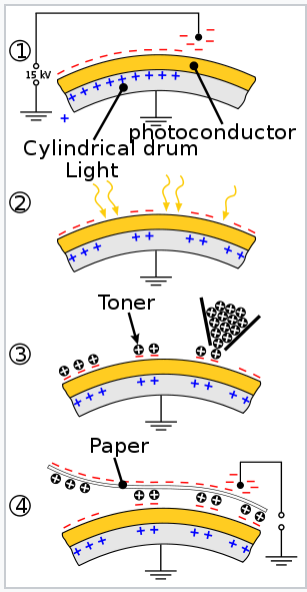
    The photoconductivity of amorphous Se is exploited in xerography. A conductive drum coated with a-Se, which is insulating, is charged with static electricity by corona discharge from a wire. When the drum is exposed to a pattern of light and dark (the image to be duplicated), the illuminated a-Se areas become conductive and the static charge is dissipated from those parts of the drum. Carbon-containing toner particles then adhere via static charge to the areas that were not exposed to light, and are transferred and bonded to paper to make the copy. The speed of the process and the high resolution of pattern transfer depend on the very low conductivity of a-Se in the dark and its high conductivity under illumination.

    clipboard_e8371b703127ff3febcd03f586d396851.png

    Charging of amorphous Se and pattern transfer in the xerographic cycle.

    Amorphous hydrogenated Si is used in inexpensive thin film solar cells. The mobility gap is about 1.7 eV, which is larger than the bandgap crystalline of Si (1.1 eV). a-Si:H is a direct-gap material, and therefore thin films are good light absorbers. a-Si:H solar cells can be vapor-deposited in large-area sheets. p+Si-a-Si:H-n+Si cells have around 10% power conversion efficiency. However amorphous Si solar cells gradually lose efficiency as they are exposed to light. The mechanism of this efficiency loss, called the Staebler-Wronski effect,[9], involves photogenerated electron-hole pairs which have sufficient energy to cause chemical changes in the material. While the exact mechanism is still unclear, it has been proposed that the energy of electron-hole recombination breaks a weak Si-Si bond, and that one of the resulting dangling bonds abstracts a H atom, leaving a passivated Si-H center and a permanent dangling bond. The effect is minimized by hydrogenating a-Si and can be partially reversed by annealing.

    clipboard_e81ba9becaa9f3f9a7761655e14cb6d41.png

    A calculator that runs on solar and battery power

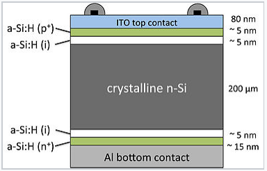
    Thin layers of amorphous silicon are used in conjunction with crystalline silicon in heterojunction intrinsic thin-layer (HIT) solar cells.[10] Because the mobility gap of a-Si is wider than the bandgap of c-Si, there is a potential energy barrier at the amorphous-crystalline interface that reflects electrons and holes away from that interface. At the p+ contact, only holes can tunnel through the barrier, whereas only electrons can tunnel through the barrier to the n+ contact. The passivation of surface defects that are sites of electron-hole recombination prevents a major loss mechanism in solar cells, increasing both the photovoltage and the photocurrent relative to conventional c-Si p-n junction cells. Panasonic and Sanyo have announced the production of HIT cells with power conversion efficiencies as high as 23%.

    clipboard_ed3be077f04fbed7f4ca7b03a127d75ae.png

    Layered structure of a HIT solar cell. The layers are not drawn to scale. A thick crystalline n-silicon layer is the light absorber, and photogenerated holes, which are the minority carriers, are reflected away from the aluminum back contact by the thin intrinsic a-Si layer there.


    9.12: Amorphous Semiconductors is shared under a CC BY-SA license and was authored, remixed, and/or curated by LibreTexts.

    • Was this article helpful?