3.15: Covalent Bonding: Drawing Lewis Structures of Covalent Molecules
- Page ID
- 215724
\( \newcommand{\vecs}[1]{\overset { \scriptstyle \rightharpoonup} {\mathbf{#1}} } \)
\( \newcommand{\vecd}[1]{\overset{-\!-\!\rightharpoonup}{\vphantom{a}\smash {#1}}} \)
\( \newcommand{\id}{\mathrm{id}}\) \( \newcommand{\Span}{\mathrm{span}}\)
( \newcommand{\kernel}{\mathrm{null}\,}\) \( \newcommand{\range}{\mathrm{range}\,}\)
\( \newcommand{\RealPart}{\mathrm{Re}}\) \( \newcommand{\ImaginaryPart}{\mathrm{Im}}\)
\( \newcommand{\Argument}{\mathrm{Arg}}\) \( \newcommand{\norm}[1]{\| #1 \|}\)
\( \newcommand{\inner}[2]{\langle #1, #2 \rangle}\)
\( \newcommand{\Span}{\mathrm{span}}\)
\( \newcommand{\id}{\mathrm{id}}\)
\( \newcommand{\Span}{\mathrm{span}}\)
\( \newcommand{\kernel}{\mathrm{null}\,}\)
\( \newcommand{\range}{\mathrm{range}\,}\)
\( \newcommand{\RealPart}{\mathrm{Re}}\)
\( \newcommand{\ImaginaryPart}{\mathrm{Im}}\)
\( \newcommand{\Argument}{\mathrm{Arg}}\)
\( \newcommand{\norm}[1]{\| #1 \|}\)
\( \newcommand{\inner}[2]{\langle #1, #2 \rangle}\)
\( \newcommand{\Span}{\mathrm{span}}\) \( \newcommand{\AA}{\unicode[.8,0]{x212B}}\)
\( \newcommand{\vectorA}[1]{\vec{#1}} % arrow\)
\( \newcommand{\vectorAt}[1]{\vec{\text{#1}}} % arrow\)
\( \newcommand{\vectorB}[1]{\overset { \scriptstyle \rightharpoonup} {\mathbf{#1}} } \)
\( \newcommand{\vectorC}[1]{\textbf{#1}} \)
\( \newcommand{\vectorD}[1]{\overrightarrow{#1}} \)
\( \newcommand{\vectorDt}[1]{\overrightarrow{\text{#1}}} \)
\( \newcommand{\vectE}[1]{\overset{-\!-\!\rightharpoonup}{\vphantom{a}\smash{\mathbf {#1}}}} \)
\( \newcommand{\vecs}[1]{\overset { \scriptstyle \rightharpoonup} {\mathbf{#1}} } \)
\( \newcommand{\vecd}[1]{\overset{-\!-\!\rightharpoonup}{\vphantom{a}\smash {#1}}} \)
\(\newcommand{\avec}{\mathbf a}\) \(\newcommand{\bvec}{\mathbf b}\) \(\newcommand{\cvec}{\mathbf c}\) \(\newcommand{\dvec}{\mathbf d}\) \(\newcommand{\dtil}{\widetilde{\mathbf d}}\) \(\newcommand{\evec}{\mathbf e}\) \(\newcommand{\fvec}{\mathbf f}\) \(\newcommand{\nvec}{\mathbf n}\) \(\newcommand{\pvec}{\mathbf p}\) \(\newcommand{\qvec}{\mathbf q}\) \(\newcommand{\svec}{\mathbf s}\) \(\newcommand{\tvec}{\mathbf t}\) \(\newcommand{\uvec}{\mathbf u}\) \(\newcommand{\vvec}{\mathbf v}\) \(\newcommand{\wvec}{\mathbf w}\) \(\newcommand{\xvec}{\mathbf x}\) \(\newcommand{\yvec}{\mathbf y}\) \(\newcommand{\zvec}{\mathbf z}\) \(\newcommand{\rvec}{\mathbf r}\) \(\newcommand{\mvec}{\mathbf m}\) \(\newcommand{\zerovec}{\mathbf 0}\) \(\newcommand{\onevec}{\mathbf 1}\) \(\newcommand{\real}{\mathbb R}\) \(\newcommand{\twovec}[2]{\left[\begin{array}{r}#1 \\ #2 \end{array}\right]}\) \(\newcommand{\ctwovec}[2]{\left[\begin{array}{c}#1 \\ #2 \end{array}\right]}\) \(\newcommand{\threevec}[3]{\left[\begin{array}{r}#1 \\ #2 \\ #3 \end{array}\right]}\) \(\newcommand{\cthreevec}[3]{\left[\begin{array}{c}#1 \\ #2 \\ #3 \end{array}\right]}\) \(\newcommand{\fourvec}[4]{\left[\begin{array}{r}#1 \\ #2 \\ #3 \\ #4 \end{array}\right]}\) \(\newcommand{\cfourvec}[4]{\left[\begin{array}{c}#1 \\ #2 \\ #3 \\ #4 \end{array}\right]}\) \(\newcommand{\fivevec}[5]{\left[\begin{array}{r}#1 \\ #2 \\ #3 \\ #4 \\ #5 \\ \end{array}\right]}\) \(\newcommand{\cfivevec}[5]{\left[\begin{array}{c}#1 \\ #2 \\ #3 \\ #4 \\ #5 \\ \end{array}\right]}\) \(\newcommand{\mattwo}[4]{\left[\begin{array}{rr}#1 \amp #2 \\ #3 \amp #4 \\ \end{array}\right]}\) \(\newcommand{\laspan}[1]{\text{Span}\{#1\}}\) \(\newcommand{\bcal}{\cal B}\) \(\newcommand{\ccal}{\cal C}\) \(\newcommand{\scal}{\cal S}\) \(\newcommand{\wcal}{\cal W}\) \(\newcommand{\ecal}{\cal E}\) \(\newcommand{\coords}[2]{\left\{#1\right\}_{#2}}\) \(\newcommand{\gray}[1]{\color{gray}{#1}}\) \(\newcommand{\lgray}[1]{\color{lightgray}{#1}}\) \(\newcommand{\rank}{\operatorname{rank}}\) \(\newcommand{\row}{\text{Row}}\) \(\newcommand{\col}{\text{Col}}\) \(\renewcommand{\row}{\text{Row}}\) \(\newcommand{\nul}{\text{Nul}}\) \(\newcommand{\var}{\text{Var}}\) \(\newcommand{\corr}{\text{corr}}\) \(\newcommand{\len}[1]{\left|#1\right|}\) \(\newcommand{\bbar}{\overline{\bvec}}\) \(\newcommand{\bhat}{\widehat{\bvec}}\) \(\newcommand{\bperp}{\bvec^\perp}\) \(\newcommand{\xhat}{\widehat{\xvec}}\) \(\newcommand{\vhat}{\widehat{\vvec}}\) \(\newcommand{\uhat}{\widehat{\uvec}}\) \(\newcommand{\what}{\widehat{\wvec}}\) \(\newcommand{\Sighat}{\widehat{\Sigma}}\) \(\newcommand{\lt}{<}\) \(\newcommand{\gt}{>}\) \(\newcommand{\amp}{&}\) \(\definecolor{fillinmathshade}{gray}{0.9}\)- Distinguish between paired and unpaired electrons.
- Explain how electrons are shared between atoms.
- Draw Lewis structures of covalent molecules.
Electron dot structures, which were discussed in the previous chapter, visually represent the valence electrons that are present in an atom as dots that are written around an elemental symbol. If two electrons are written on the same "side" of the electron dot structure, they are known as paired electrons. Therefore, an unpaired electron must exist alone on a particular "side" of an electron dot structure. An electron dot structure for sulfur, which contains both paired and unpaired electrons, is shown below in Figure \(\PageIndex{1}\).
.png?revision=1)
The presence of unpaired electrons within an atom is inherently destabilizing. Therefore, if two atoms that contain unpaired electrons approach one another, those electrons will interact with one another to form a shared pair of electrons. The resultant covalent, or molecular, bond is drawn as a line in a two-dimensional picture called a Lewis structure. These structural images are named after Gilbert Lewis, the American chemist who first proposed that covalent molecules could be represented visually. Any paired electrons that are present in an atom are already sufficiently stable and, consequently, do not form bonds. Instead, those electrons will remain as lone, or unshared, pairs, which are represented as dots in Lewis structures. A covalent molecule is formed once all of the involved atoms have achieved stable electron configurations. The process for drawing the Lewis structure of a covalent molecule will be described in the following paragraphs.
Drawing Lewis Structures of Covalent Molecules
After establishing that a pair of chemicals will form an ionic bond, a five-step process was employed to determine the chemical formula of the resultant ionic compound, and this chemical formula was used to derive a corresponding chemical name. However, because ionic and covalent bonds are created through completely-unrelated electronic interactions, the procedures that will be outlined for covalent molecules will be fundamentally different than the ionic processes that have been previously discussed. Covalent bonds are produced when unpaired electrons found within two atoms interact to form a shared pair of electrons. Accurately executing this sharing process is essential to the development of a chemically-correct covalent molecule. Therefore, a Lewis structure must be drawn for a covalent molecule before its chemical formula can be determined.
For example, consider fluorine and sulfur.
Based on the combinations listed in Section 3.14, fluorine and sulfur, which are both non-metals, will combine to form a covalent molecule. After establishing that a pair of elements will bond covalently, a four-step process can be employed to draw the Lewis structure of the resultant molecule.
- Draw a valid electron dot structure for each of the given elements. Since fluorine is found in Group 7A of the periodic table, it contains 7 valence electrons. Sulfur, which is located in Group 6A, has 6 valence electrons. A chemically-correct electron dot structure for each of these elements is shown below.
Recall that the first four dots in an electron dot structure must each be placed on their own "side" of the elemental symbol, and the "sides" can be utilized in any order. Each additional dot can be placed using analogous rules. Therefore, several valid electron dot structures could have been drawn for each of the given elements.
- Count the number of unpaired electrons that are present in each electron dot structure, in order to determine the relative placement of each element within the final molecule. Based on the structures shown above, fluorine contains 1 unpaired electron, and sulfur has 2 unpaired electrons. The number of paired electrons that each element possesses is unimportant, as these electrons are sufficiently stable and, consequently, do not form bonds.
- The element with more unpaired electrons will become the central atom in a Lewis structure, as it is drawn in the middle of any other atoms that are present. Only a single central atom should be utilized for most covalent molecules. The other element will be used as a surrounding atom, because its electron dot structures will be located around the central atom. One surrounding atom should be paired with each of the central atom's unpaired electrons, in order to create a shared pair of electrons. As the central atom in a covalent molecule usually has more than one unpaired valence electron, multiple surrounding atoms are generally used in the pairing process.
When executing this step, the electron dot structure for the surrounding atom should be rotated so that its unpaired electron aligns with an unpaired electron on the central atom. Because the dots on an electron dot structure can be placed on any "side" of the elemental symbol, this rotation changes the orientation of the structure, but does not alter its meaning.
In the current example, sulfur has more unpaired electrons than fluorine. Therefore, sulfur is the central atom, and fluorine is used as the surrounding atom. Since sulfur's unpaired electrons are located on the left and bottom "sides" of the electron dot structure that is shown above, one electron dot structure for fluorine should be placed in each of these locations. Note that an electron dot structure for fluorine should not be placed on either the top or right "sides" of sulfur's electron dot structure, as stable electron pairs already exist in each of those locations. The resultant structure is shown below.
This structure contains two shared pairs of electrons, which are located on the left and bottom "sides" of sulfur's electron dot structure. Each of these shared pairs was created by pairing one of sulfur's unpaired electrons with an unpaired electron from fluorine. As these electron pairs are written between two elemental symbols, these electrons contribute to the overall electron configuration of both atoms. The remaining electrons only impact the electron configuration of the atom on which they are drawn.
Recall that the ultimate goal of bonding is to achieve stable electron configurations for all of the given elements. As has been stated several times, electrons are most stable when they exist in pairs. Note that by correctly executing this pairing process, all of the electrons in the structure shown above are paired. Furthermore, each atom in this structure possesses an octet, as each elemental symbol is surrounded by a total of eight, fully-paired dots. This information is visually-highlighted in the structure shown below using a blue circle around sulfur and a green box around each fluorine. As an octet configuration is the most stable electron arrangement that can be achieved by an atom, this structure represents the most stable bonding arrangement that can be achieved by combining fluorine and sulfur.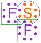
- While chemically-correct, the structure shown above is visually-dense, as many dots are written in close physical proximity to one another. In order to generate a structure that is more visually-appealing, each shared pair of electrons is replaced with a line that connects the adjacent elemental symbols. The remaining electrons are redrawn as dots on the resultant structure, as shown below.
In the structure that is generated upon the completion of this final step, each line represents a covalent bond, or a shared pair of electrons, and the remaining pairs of dots are called lone pairs. The structure shown above, which is a chemically-correct representation of a covalent compound, is a Lewis structure that represents the molecule that is formed when fluorine and sulfur bond with one another.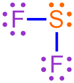
Draw the Lewis structure that represents the compound that is formed when carbon and chlorine bond with one another.
Solution
Based on the combinations listed in Section 3.14, carbon and chlorine, which are both non-metals, will combine to form a covalent molecule. Carbon, which is located in Group 4A, has 4 valence electrons. Since chlorine is found in Group 7A of the periodic table, it contains 7 valence electrons. A chemically-correct electron dot structure for each of these elements is shown below.

Based on the structures shown above, carbon has 4 unpaired electrons, and chlorine contains 1 unpaired electron. The element with more unpaired electrons will become the central atom in a Lewis structure, as it is drawn in the middle of any other atoms that are present. Only a single central atom should be utilized for most covalent molecules. The other element will be used as a surrounding atom, because its electron dot structures will be located around the central atom. One surrounding atom should be paired with each of the central atom's unpaired electrons, in order to create a shared pair of electrons. As the central atom in a covalent molecule usually has more than one unpaired valence electron, multiple surrounding atoms are generally used in the pairing process.
When executing this pairing step, the electron dot structure for the surrounding atom should be rotated so that its unpaired electron aligns with an unpaired electron on the central atom. Because the dots on an electron dot structure can be placed on any "side" of the elemental symbol, this rotation changes the orientation of the structure, but does not alter its meaning.
In the current example, carbon has more unpaired electrons than chlorine. Therefore, carbon is the central atom, and chlorine is used as the surrounding atom. Since carbon has an unpaired electron on all four "sides" of the electron dot structure that is shown above, one electron dot structure for chlorine should be placed in each of these locations. The resultant structure is shown below.
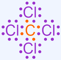
This structure contains four shared pairs of electrons, which are located on all four "sides" of carbon's electron dot structure. Each of these shared pairs was created by pairing one of carbon's unpaired electrons with an unpaired electron from chlorine. As these electron pairs are written between two elemental symbols, these electrons contribute to the overall electron configuration of both atoms. The remaining electrons only impact the electron configuration of the atom on which they are drawn.
Note that by correctly executing this pairing process, each elemental symbol in this structure is surrounded by a total of eight, fully-paired dots. This information is visually-highlighted in the structure shown below using a blue circle around carbon and a green box around each chlorine. As an octet configuration is the most stable electron arrangement that can be achieved by an atom, this structure represents the most stable bonding arrangement that can be achieved by combining carbon and chlorine.

While chemically-correct, the structure shown above is visually-dense, as many dots are written in close physical proximity to one another. In order to generate a structure that is more visually-appealing, each shared pair of electrons is replaced with a line that connects the adjacent elemental symbols. The remaining electrons are redrawn as dots on the resultant structure, as shown below.
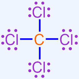
In the structure that is generated upon the completion of this final step, each line represents a covalent bond, or a shared pair of electrons, and the remaining pairs of dots are called lone pairs. The structure shown above, which is a chemically-correct representation of a covalent compound, is the Lewis structure that represents the molecule that is formed when carbon and chlorine bond with one another.
Draw a Lewis structure that represents the compound that is formed when bromine and phosphorus bond with one another.
- Answer
- Based on the combinations listed in Section 3.14, bromine and phosphorus, which are both non-metals, will combine to form a covalent molecule. Since bromine is found in Group 7A of the periodic table, it contains 7 valence electrons. Phosphorus, which is located in Group 5A, has 5 valence electrons. A chemically-correct electron dot structure for each of these elements is shown below.
Based on the structures shown above, bromine contains 1 unpaired electron, and phosphorus has 3 unpaired electrons. The element with more unpaired electrons will become the central atom in a Lewis structure, and the other element will be used as a surrounding atom. One surrounding atom should be paired with each of the central atom's unpaired electrons, in order to create a shared pair of electrons. When executing this pairing step, the electron dot structure for the surrounding atom should be rotated so that its unpaired electron aligns with an unpaired electron on the central atom. Because the dots on an electron dot structure can be placed on any "side" of the elemental symbol, this rotation changes the orientation of the structure, but does not alter its meaning.
In the current example, phosphorus has more unpaired electrons than bromine. Therefore, phosphorus is the central atom, and bromine is used as the surrounding atom. Since phosphorus's unpaired electrons are located on the left, right, and bottom "sides" of the electron dot structure that is shown above, one electron dot structure for bromine should be placed in each of these locations. Note that an electron dot structure for bromine should not be placed on the top "side" of phosphorus's electron dot structure, as a stable electron pair already exists in that location. The resultant structure is shown below.
This structure contains three shared pairs of electrons, which are located on the left, right, and bottom "sides" of phosphorus's electron dot structure. Each of these shared pairs was created by pairing one of phosphorus's unpaired electrons with an unpaired electron from bromine. As these electron pairs are written between two elemental symbols, these electrons contribute to the overall electron configuration of both atoms. The remaining electrons only impact the electron configuration of the atom on which they are drawn.
Note that by correctly executing this pairing process, each elemental symbol in this structure is surrounded by a total of eight, fully-paired dots. This information is visually-highlighted in the structure shown below using a blue circle around phosphorus and a green box around each bromine. As an octet configuration is the most stable electron arrangement that can be achieved by an atom, this structure represents the most stable bonding arrangement that can be achieved by combining bromine and phosphorus.
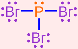
In order to generate a structure that is more visually-appealing, each shared pair of electrons is replaced with a line that connects the adjacent elemental symbols. The remaining electrons are redrawn as dots on the resultant structure, as shown below.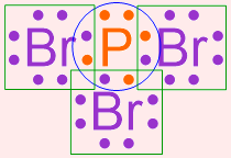
In the structure that is generated upon the completion of this final step, each line represents a covalent bond, or a shared pair of electrons, and the remaining pairs of dots are called lone pairs. The structure shown above, which is a chemically-correct representation of a covalent compound, is a Lewis structure that represents the molecule that is formed when bromine and phosphorus bond with one another.