
4.2: Lewis (Electron-Dot) Symbols
- Page ID
- 440228
\( \newcommand{\vecs}[1]{\overset { \scriptstyle \rightharpoonup} {\mathbf{#1}} } \)
\( \newcommand{\vecd}[1]{\overset{-\!-\!\rightharpoonup}{\vphantom{a}\smash {#1}}} \)
\( \newcommand{\dsum}{\displaystyle\sum\limits} \)
\( \newcommand{\dint}{\displaystyle\int\limits} \)
\( \newcommand{\dlim}{\displaystyle\lim\limits} \)
\( \newcommand{\id}{\mathrm{id}}\) \( \newcommand{\Span}{\mathrm{span}}\)
( \newcommand{\kernel}{\mathrm{null}\,}\) \( \newcommand{\range}{\mathrm{range}\,}\)
\( \newcommand{\RealPart}{\mathrm{Re}}\) \( \newcommand{\ImaginaryPart}{\mathrm{Im}}\)
\( \newcommand{\Argument}{\mathrm{Arg}}\) \( \newcommand{\norm}[1]{\| #1 \|}\)
\( \newcommand{\inner}[2]{\langle #1, #2 \rangle}\)
\( \newcommand{\Span}{\mathrm{span}}\)
\( \newcommand{\id}{\mathrm{id}}\)
\( \newcommand{\Span}{\mathrm{span}}\)
\( \newcommand{\kernel}{\mathrm{null}\,}\)
\( \newcommand{\range}{\mathrm{range}\,}\)
\( \newcommand{\RealPart}{\mathrm{Re}}\)
\( \newcommand{\ImaginaryPart}{\mathrm{Im}}\)
\( \newcommand{\Argument}{\mathrm{Arg}}\)
\( \newcommand{\norm}[1]{\| #1 \|}\)
\( \newcommand{\inner}[2]{\langle #1, #2 \rangle}\)
\( \newcommand{\Span}{\mathrm{span}}\) \( \newcommand{\AA}{\unicode[.8,0]{x212B}}\)
\( \newcommand{\vectorA}[1]{\vec{#1}} % arrow\)
\( \newcommand{\vectorAt}[1]{\vec{\text{#1}}} % arrow\)
\( \newcommand{\vectorB}[1]{\overset { \scriptstyle \rightharpoonup} {\mathbf{#1}} } \)
\( \newcommand{\vectorC}[1]{\textbf{#1}} \)
\( \newcommand{\vectorD}[1]{\overrightarrow{#1}} \)
\( \newcommand{\vectorDt}[1]{\overrightarrow{\text{#1}}} \)
\( \newcommand{\vectE}[1]{\overset{-\!-\!\rightharpoonup}{\vphantom{a}\smash{\mathbf {#1}}}} \)
\( \newcommand{\vecs}[1]{\overset { \scriptstyle \rightharpoonup} {\mathbf{#1}} } \)
\(\newcommand{\longvect}{\overrightarrow}\)
\( \newcommand{\vecd}[1]{\overset{-\!-\!\rightharpoonup}{\vphantom{a}\smash {#1}}} \)
\(\newcommand{\avec}{\mathbf a}\) \(\newcommand{\bvec}{\mathbf b}\) \(\newcommand{\cvec}{\mathbf c}\) \(\newcommand{\dvec}{\mathbf d}\) \(\newcommand{\dtil}{\widetilde{\mathbf d}}\) \(\newcommand{\evec}{\mathbf e}\) \(\newcommand{\fvec}{\mathbf f}\) \(\newcommand{\nvec}{\mathbf n}\) \(\newcommand{\pvec}{\mathbf p}\) \(\newcommand{\qvec}{\mathbf q}\) \(\newcommand{\svec}{\mathbf s}\) \(\newcommand{\tvec}{\mathbf t}\) \(\newcommand{\uvec}{\mathbf u}\) \(\newcommand{\vvec}{\mathbf v}\) \(\newcommand{\wvec}{\mathbf w}\) \(\newcommand{\xvec}{\mathbf x}\) \(\newcommand{\yvec}{\mathbf y}\) \(\newcommand{\zvec}{\mathbf z}\) \(\newcommand{\rvec}{\mathbf r}\) \(\newcommand{\mvec}{\mathbf m}\) \(\newcommand{\zerovec}{\mathbf 0}\) \(\newcommand{\onevec}{\mathbf 1}\) \(\newcommand{\real}{\mathbb R}\) \(\newcommand{\twovec}[2]{\left[\begin{array}{r}#1 \\ #2 \end{array}\right]}\) \(\newcommand{\ctwovec}[2]{\left[\begin{array}{c}#1 \\ #2 \end{array}\right]}\) \(\newcommand{\threevec}[3]{\left[\begin{array}{r}#1 \\ #2 \\ #3 \end{array}\right]}\) \(\newcommand{\cthreevec}[3]{\left[\begin{array}{c}#1 \\ #2 \\ #3 \end{array}\right]}\) \(\newcommand{\fourvec}[4]{\left[\begin{array}{r}#1 \\ #2 \\ #3 \\ #4 \end{array}\right]}\) \(\newcommand{\cfourvec}[4]{\left[\begin{array}{c}#1 \\ #2 \\ #3 \\ #4 \end{array}\right]}\) \(\newcommand{\fivevec}[5]{\left[\begin{array}{r}#1 \\ #2 \\ #3 \\ #4 \\ #5 \\ \end{array}\right]}\) \(\newcommand{\cfivevec}[5]{\left[\begin{array}{c}#1 \\ #2 \\ #3 \\ #4 \\ #5 \\ \end{array}\right]}\) \(\newcommand{\mattwo}[4]{\left[\begin{array}{rr}#1 \amp #2 \\ #3 \amp #4 \\ \end{array}\right]}\) \(\newcommand{\laspan}[1]{\text{Span}\{#1\}}\) \(\newcommand{\bcal}{\cal B}\) \(\newcommand{\ccal}{\cal C}\) \(\newcommand{\scal}{\cal S}\) \(\newcommand{\wcal}{\cal W}\) \(\newcommand{\ecal}{\cal E}\) \(\newcommand{\coords}[2]{\left\{#1\right\}_{#2}}\) \(\newcommand{\gray}[1]{\color{gray}{#1}}\) \(\newcommand{\lgray}[1]{\color{lightgray}{#1}}\) \(\newcommand{\rank}{\operatorname{rank}}\) \(\newcommand{\row}{\text{Row}}\) \(\newcommand{\col}{\text{Col}}\) \(\renewcommand{\row}{\text{Row}}\) \(\newcommand{\nul}{\text{Nul}}\) \(\newcommand{\var}{\text{Var}}\) \(\newcommand{\corr}{\text{corr}}\) \(\newcommand{\len}[1]{\left|#1\right|}\) \(\newcommand{\bbar}{\overline{\bvec}}\) \(\newcommand{\bhat}{\widehat{\bvec}}\) \(\newcommand{\bperp}{\bvec^\perp}\) \(\newcommand{\xhat}{\widehat{\xvec}}\) \(\newcommand{\vhat}{\widehat{\vvec}}\) \(\newcommand{\uhat}{\widehat{\uvec}}\) \(\newcommand{\what}{\widehat{\wvec}}\) \(\newcommand{\Sighat}{\widehat{\Sigma}}\) \(\newcommand{\lt}{<}\) \(\newcommand{\gt}{>}\) \(\newcommand{\amp}{&}\) \(\definecolor{fillinmathshade}{gray}{0.9}\)- Draw a Lewis electron dot diagram for an atom.
- Know the importance of Lewis dot in bonding.
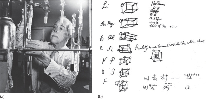
At the beginning of the 20th century, an American physical chemist G. N. Lewis (1875–1946) devised a system of symbols—now called Lewis electron dot symbols (often shortened to Lewis dot symbols) that can be used for predicting the number of bonds formed by most elements in their compounds.
- convenient representation of valence electrons
- allows scientists to keep track of valence electrons during bond formation
- consists of the atomic symbol for the element plus a dot for each valence electron
To write an element’s Lewis dot symbol, we place dots representing its valence electrons, one at a time, around the element’s chemical symbol. Up to four dots are placed above, below, to the left, and to the right of the symbol (in any order, as long as elements with four or fewer valence electrons have no more than one dot in each position). The next dots, for elements with more than four valence electrons, are again distributed one at a time, each paired with one of the first four. For example, the element sulfur has six valence electrons (note roman numeral above group on the periodic table) and its Lewis symbol would be:
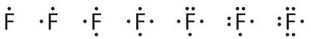
Fluorine, for example, has seven valence electrons, so its Lewis dot symbol is constructed as follows:
Lewis eventually published his theory of chemical bonding in 1916. Formation of chemical bonds to complete the requirement of eight electrons for the atom becomes a natural tendency. Lewis dot symbols of the first two periods are given here to illustrate this point. In fact, the entire group (column) of elements have the same Lewis dot symbols, because they have the same number of valence electrons.
By going through the periodic table, we see that the Lewis electron dot symbols of atoms will never have more than eight dots around the atomic symbo see Table \(\PageIndex{1}\).
| \(\ce{H\cdot}\) | \(\textrm{He:}\) | ||||||
|---|---|---|---|---|---|---|---|
\(\underset{\:}{\ce{Li\cdot}}\) |
\(\underset{\:}{\ce{\cdot Be \cdot}}\) |
\(\ce{ \cdot \underset{\:}{\overset{\Large{\cdot}}{B}} \cdot}\) |
\(\ce{ \cdot \underset{\Large{\cdot}}{\overset{\Large{\cdot}}{C}} \cdot}\) |
\( \underset{\Large{\cdot\,}} {\overset{\Large{\cdot}} {\textrm{:N}\cdot}} \) |
\( \underset{\Large{\cdot\cdot\,}} {\overset{\Large{\cdot}} {\textrm{:O}\cdot}} \) |
\( \underset{\Large{\cdot\cdot}} {\overset{\Large{\cdot\cdot}} {\textrm{:F}\cdot}} \) |
\( \underset{\Large{\cdot\cdot}} {\overset{\Large{\cdot\cdot}}{\textrm{:Ne:}}} \) |
| \(\ce{Na}\) \(\ce{K}\) \(\ce{Rb}\) \(\ce{Cs}\) |
\(\ce{Mg}\) \(\ce{Ca}\) \(\ce{Sr}\) \(\ce{Ba}\) |
\(\ce{Al}\) \(\ce{Ga}\) \(\ce{In}\) \(\ce{Tl}\) |
\(\ce{Si}\) \(\ce{Ge}\) \(\ce{Sn}\) \(\ce{Pb}\) |
\(\ce{P}\) \(\ce{As}\) \(\ce{Sb}\) \(\ce{Bi}\) |
\(\ce{S}\) \(\ce{Se}\) \(\ce{Te}\) \(\ce{Po}\) |
\(\ce{Cl}\) \(\ce{Br}\) \(\ce{I}\) \(\ce{At}\) |
\(\ce{Ar}\) \(\ce{Kr}\) \(\ce{At}\) \(\ce{Rn}\) |
What is the Lewis electron dot diagram for each element?
- aluminum
- selenium
Solution
- The valence electron configuration for aluminum is 3s23p1. So it would have three dots around the symbol for aluminum, two of them paired to represent the 3s electrons:
\[\dot{Al:} \nonumber \]
- The valence electron configuration for selenium is 4s24p4. In the highest-numbered shell, the n = 4 shell, there are six electrons. Its electron dot diagram is as follows:
\[\mathbf{\cdot }\mathbf{\dot{\underset{.\: .}Se}}\mathbf{:} \nonumber \]
What is the Lewis electron dot diagram for each element?
- phosphorus
- argon
- Answer a
-
\[\mathbf{\cdot }\mathbf{\dot{\underset{.}P}}\mathbf{:} \nonumber \]
- Answer b
-
\[\mathbf{:}\mathbf{\ddot{\underset{.\, .}Ar}}\mathbf{:} \nonumber \]
Summary
- Lewis electron dot diagrams use dots to represent valence electrons around an atomic symbol.
- Lewis dot symbols can be used to predict the number of bonds formed by elements in a compound.
Contributors and Attributions
- Wikipedia
- National Programme on Technology Enhanced Learning (India)
Isabella Quiros (Furman University)