
X-ray Diffraction
- Page ID
- 315
\( \newcommand{\vecs}[1]{\overset { \scriptstyle \rightharpoonup} {\mathbf{#1}} } \)
\( \newcommand{\vecd}[1]{\overset{-\!-\!\rightharpoonup}{\vphantom{a}\smash {#1}}} \)
\( \newcommand{\dsum}{\displaystyle\sum\limits} \)
\( \newcommand{\dint}{\displaystyle\int\limits} \)
\( \newcommand{\dlim}{\displaystyle\lim\limits} \)
\( \newcommand{\id}{\mathrm{id}}\) \( \newcommand{\Span}{\mathrm{span}}\)
( \newcommand{\kernel}{\mathrm{null}\,}\) \( \newcommand{\range}{\mathrm{range}\,}\)
\( \newcommand{\RealPart}{\mathrm{Re}}\) \( \newcommand{\ImaginaryPart}{\mathrm{Im}}\)
\( \newcommand{\Argument}{\mathrm{Arg}}\) \( \newcommand{\norm}[1]{\| #1 \|}\)
\( \newcommand{\inner}[2]{\langle #1, #2 \rangle}\)
\( \newcommand{\Span}{\mathrm{span}}\)
\( \newcommand{\id}{\mathrm{id}}\)
\( \newcommand{\Span}{\mathrm{span}}\)
\( \newcommand{\kernel}{\mathrm{null}\,}\)
\( \newcommand{\range}{\mathrm{range}\,}\)
\( \newcommand{\RealPart}{\mathrm{Re}}\)
\( \newcommand{\ImaginaryPart}{\mathrm{Im}}\)
\( \newcommand{\Argument}{\mathrm{Arg}}\)
\( \newcommand{\norm}[1]{\| #1 \|}\)
\( \newcommand{\inner}[2]{\langle #1, #2 \rangle}\)
\( \newcommand{\Span}{\mathrm{span}}\) \( \newcommand{\AA}{\unicode[.8,0]{x212B}}\)
\( \newcommand{\vectorA}[1]{\vec{#1}} % arrow\)
\( \newcommand{\vectorAt}[1]{\vec{\text{#1}}} % arrow\)
\( \newcommand{\vectorB}[1]{\overset { \scriptstyle \rightharpoonup} {\mathbf{#1}} } \)
\( \newcommand{\vectorC}[1]{\textbf{#1}} \)
\( \newcommand{\vectorD}[1]{\overrightarrow{#1}} \)
\( \newcommand{\vectorDt}[1]{\overrightarrow{\text{#1}}} \)
\( \newcommand{\vectE}[1]{\overset{-\!-\!\rightharpoonup}{\vphantom{a}\smash{\mathbf {#1}}}} \)
\( \newcommand{\vecs}[1]{\overset { \scriptstyle \rightharpoonup} {\mathbf{#1}} } \)
\(\newcommand{\longvect}{\overrightarrow}\)
\( \newcommand{\vecd}[1]{\overset{-\!-\!\rightharpoonup}{\vphantom{a}\smash {#1}}} \)
\(\newcommand{\avec}{\mathbf a}\) \(\newcommand{\bvec}{\mathbf b}\) \(\newcommand{\cvec}{\mathbf c}\) \(\newcommand{\dvec}{\mathbf d}\) \(\newcommand{\dtil}{\widetilde{\mathbf d}}\) \(\newcommand{\evec}{\mathbf e}\) \(\newcommand{\fvec}{\mathbf f}\) \(\newcommand{\nvec}{\mathbf n}\) \(\newcommand{\pvec}{\mathbf p}\) \(\newcommand{\qvec}{\mathbf q}\) \(\newcommand{\svec}{\mathbf s}\) \(\newcommand{\tvec}{\mathbf t}\) \(\newcommand{\uvec}{\mathbf u}\) \(\newcommand{\vvec}{\mathbf v}\) \(\newcommand{\wvec}{\mathbf w}\) \(\newcommand{\xvec}{\mathbf x}\) \(\newcommand{\yvec}{\mathbf y}\) \(\newcommand{\zvec}{\mathbf z}\) \(\newcommand{\rvec}{\mathbf r}\) \(\newcommand{\mvec}{\mathbf m}\) \(\newcommand{\zerovec}{\mathbf 0}\) \(\newcommand{\onevec}{\mathbf 1}\) \(\newcommand{\real}{\mathbb R}\) \(\newcommand{\twovec}[2]{\left[\begin{array}{r}#1 \\ #2 \end{array}\right]}\) \(\newcommand{\ctwovec}[2]{\left[\begin{array}{c}#1 \\ #2 \end{array}\right]}\) \(\newcommand{\threevec}[3]{\left[\begin{array}{r}#1 \\ #2 \\ #3 \end{array}\right]}\) \(\newcommand{\cthreevec}[3]{\left[\begin{array}{c}#1 \\ #2 \\ #3 \end{array}\right]}\) \(\newcommand{\fourvec}[4]{\left[\begin{array}{r}#1 \\ #2 \\ #3 \\ #4 \end{array}\right]}\) \(\newcommand{\cfourvec}[4]{\left[\begin{array}{c}#1 \\ #2 \\ #3 \\ #4 \end{array}\right]}\) \(\newcommand{\fivevec}[5]{\left[\begin{array}{r}#1 \\ #2 \\ #3 \\ #4 \\ #5 \\ \end{array}\right]}\) \(\newcommand{\cfivevec}[5]{\left[\begin{array}{c}#1 \\ #2 \\ #3 \\ #4 \\ #5 \\ \end{array}\right]}\) \(\newcommand{\mattwo}[4]{\left[\begin{array}{rr}#1 \amp #2 \\ #3 \amp #4 \\ \end{array}\right]}\) \(\newcommand{\laspan}[1]{\text{Span}\{#1\}}\) \(\newcommand{\bcal}{\cal B}\) \(\newcommand{\ccal}{\cal C}\) \(\newcommand{\scal}{\cal S}\) \(\newcommand{\wcal}{\cal W}\) \(\newcommand{\ecal}{\cal E}\) \(\newcommand{\coords}[2]{\left\{#1\right\}_{#2}}\) \(\newcommand{\gray}[1]{\color{gray}{#1}}\) \(\newcommand{\lgray}[1]{\color{lightgray}{#1}}\) \(\newcommand{\rank}{\operatorname{rank}}\) \(\newcommand{\row}{\text{Row}}\) \(\newcommand{\col}{\text{Col}}\) \(\renewcommand{\row}{\text{Row}}\) \(\newcommand{\nul}{\text{Nul}}\) \(\newcommand{\var}{\text{Var}}\) \(\newcommand{\corr}{\text{corr}}\) \(\newcommand{\len}[1]{\left|#1\right|}\) \(\newcommand{\bbar}{\overline{\bvec}}\) \(\newcommand{\bhat}{\widehat{\bvec}}\) \(\newcommand{\bperp}{\bvec^\perp}\) \(\newcommand{\xhat}{\widehat{\xvec}}\) \(\newcommand{\vhat}{\widehat{\vvec}}\) \(\newcommand{\uhat}{\widehat{\uvec}}\) \(\newcommand{\what}{\widehat{\wvec}}\) \(\newcommand{\Sighat}{\widehat{\Sigma}}\) \(\newcommand{\lt}{<}\) \(\newcommand{\gt}{>}\) \(\newcommand{\amp}{&}\) \(\definecolor{fillinmathshade}{gray}{0.9}\)The construction of a simple powder diffractometer was first described by Hull in 19171 which was shortly after the discovery of X-rays by Wilhelm Conrad Röntgen in 18952. Diffractometer measures the angles at which X-rays get reflected and thus get the structural information they contains. Nowadays resolution of this technique get significant improvement and it is widely used as a tool to analyze the phase information and solve crystal structures of solid-state materials.
Introduction
Since the wavelength of X-rays is similar to the distance between crystal layers, incident X-rays will be diffracted, interacting with certain crystalline layers and diffraction patterns containing important structural information about the crystal can be obtained. The diffraction pattern is considered the fingerprint of the crystal because each crystal structures produce unique diffraction patterns and every phase in a mixture produces its diffraction pattern independently. We can use grinded bulk sample into fine powders, which are typical under 10 µm,2 as samples in powder X-ray Diffraction (XRD). Unlike single crystal X-ray diffraction (X-ray Crystallography) technique, the sample will distribute evenly at every possible orientation and powder XRD collects one-dimensional information, which is a diagram of diffracted beam intensity vs. Bragg angle θ, rather than three-dimensional information.
Theoretical consideration
In this section, let us take a look at the theoretical basis of powder X-ray diffraction technique. (e.g. lattice structures and how X-rays interacts with crystal structures)
Unit cells
“Crystals are built up of regular arrangements of atoms in three dimensions; these arrangements can be represented by a repeat unit or motif called the unit cell.”2 In crystallography, all the crystal unit cells can be classied into 230 space groups. Some basic knowledge about crystallography is necessary for a well understanding of powder XRD technique. In crystallography, the basic possible classifications are: 6 crystal families, 7 crystal systems, 5 centering position, 14 Bravais lattices and 32 crystal classes.
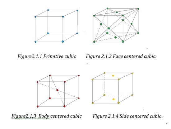
Based on the angles and the length of the axes sides, unit cell can be divided into 6 crystal families, which are cubic, tetragonal, hexagonal, orthorhombic, monoclinic and triclinic. As the hexagonal family can have two different appearances, we can divide it into two systems which are trigonal lattice and hexagonal lattice. That is how the 7 crystal systems generate. If forget the shape of lattice and just consider the atoms' positions, we can divide the lattices into primitive lattices and non-primitive ones. A primitive lattice (also defined as simple) is the lattice with the smallest possible atomic coordination number2, e.g.wheneight atoms lie in the eight corners. And all the other lattices are called non-primitive lattice. Based on the three-dimension position of the atoms in the unit cell, we can divided the non-primitive lattice into three types: face centered (F), side centered (C), body centered (I) and based centered(R).
Bravais lattice is a “combination of lattice type and crystal systems”1.And you can find a chart of examples of all the 14 Bravais lattice in outside link.
32 crystal classes refer to 32 crystallographic point group classfied by the possible symmetric operations, which are rotation, reflection and inversion. You may wonder why only 32 possible point group. The answer is crystallographic restriction, which means crystal system can only have 5 kinds of rotation axises: 1-fold, 2-fold, 3-fold, 4-fold and 6-fold. To be simplify, only the permissible rotation axises allow unit cells grow uniformly without any openings among them.
230 space groups are combinations of 14 Bravais lattice and 32 crystal classes. Those space groups are generated from translations of related Bravais lattice and glide plane and/or scew axis of relative crystal classes. They are represented by Hermann-Mauguin. For example, the NO.62 space group, Pnma is derived from D2h crystal class. P indicated it is primitive structure and n, m, a stand for a diagonal glide plane, a mirror plane and a axial glide planes. The space group belongs to orthorhombic crystal family.
Miller Indices and Reciprocal Lattice
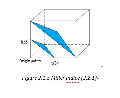
Miller indices and reciprocal lattice are essential to understanding the geometry of lattice planes and X-ray diffraction technique, because they are widely used to index the planes and orientations in crystallography and allow data handling in a simple and mathematical method. To assign the Miller indices (h,k,l) to a certain set of parallel planes which are defined as a plane family , first we need to find the first plane next to the plane, passing through the origin. Then we can find the three intersection of this plane on the unit cell vectors, a, b, c. “The Miller indices would be the reciprocals of the fractional intersections.”1 Why we want the reciprocal of fraction instead of the fraction directly? To get the answer, we need get to understand what reciprocal lattice is.
“Geometrically, the planes can be specified by two quantities: (1) their orientation in the crystal and (2) their d-spacing.” 4 (d-spacing is the interplanar distance) This allows us to use a vector d*, which is normal to the planes and whose length is inverse to d-spacing, i.e. d*=K/d 4 to stand for a certain family of planes. d* is called reciprocal lattice vector and similarly in three dimension system, reciprocal lattice vector d*hkl stand for (h,k,l). And the end point of reciprocal lattice vector form a grid or lattice- reciprocal lattice unit cell4. Reciprocal lattice cell vector a*, b*, c* is reciprocal form of direct unit cell vector a, b, c. Then it is easy to find out that d*hkl=ha*+kb*+lc*. By take the reciprocal number of the intercepts of Miller indices, those two notation systems are very consistent and straightforward in indexing the crystal lattice.
Bragg’s Law
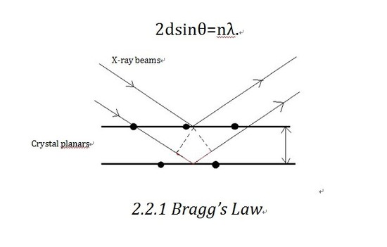
Bragg’ s law is the theoretical basis of X-ray diffractometer. Let us consider the crystalline as built up in planes. As shown in the diagram, X-ray beam shines into the planes and is reflected by different planes. The beam reflected by the lower plane will travel an extra distance (shown in Figure 2.2.1 in red)than that reflected by the upper one,which is 2dsinθ. If that distance equals nλ(n is an integer), we will get constructive interference, which corresponds to the bright contrast in diffraction pattern. So the Bragg equation as shown below defines the position of the existence of constructive diffraction at different orders.
D-spacing, which is the inter plane distance d in Bragg’s equation, is decided by the lattice parameter a, b, c, as shown below.
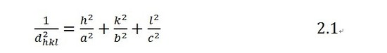
So after finding out d-spacing from detected Bragg’s angle, we can figure out the lattice parameter which contains vital structural information. Also we can reconstruct the unknown structure by figuring out all the possible d-spacing. Powder XRD can define the phase contained in a mixture on the basis of separating and recognizing characteristic diffraction pattern.
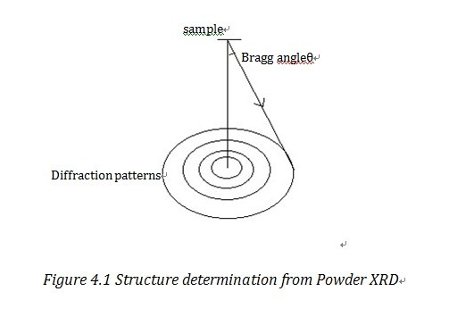
Structure factor
The sample of powder X-ray diffraction will distribute evenly at every possible orientation, so after diffracted, the diffraction pattern appears as circles with same center point instead of dots in single crystal diffraction patterns. The circles in the diffraction patterns with smaller radius correspond to smaller h, k, l. In certain types of unit cells, not all the lattice planes will have their diffraction observed, which is usually called systematic absence, because the diffracted beam may happen to be out of phase by 180°and the overall intensity would be zero. Structure factor Fhkl can decide the systematic absences and intensity.Systematic absences arise when F=0, so no diffraction will be observed. For example:
For a fcc crystal, Fhkl=f{1+eπi(h+l)+eπi(k+l)+eπi(h+k)}. When h, k, l are all odd or all even, F=4f. For the other situation, F=0 and thus diffraction intensity will also be zero. Structure factor is important in the structure determination step because it helps understand the Miller indices and intensities of diffraction peaks. The other common rules for reflection to be observed are listed as follows:
|
Lattice type |
Rule for reflection to be observed |
|---|---|
|
Primitive, P |
None |
|
Body centered, I |
hkl: h+k+l=2n |
|
Face centered, F |
hkl: h, k, l either all odd or all even |
|
Side centered, C |
hkl: h+k=2n |
|
Rhombohedral, R |
hkl: -h+k+l=3n or (h-k+l=3n) |
Instrumentation
Powder X-ray diffractometer consists of three components: X-ray source, sample holder and detector.

Source
Possible X-ray sources are X-ray tube, Synchrotron radiation and cyclotron radiation. X-ray tube equipped with filter is commonly used in laboratory diffractometer. Synchrotron radiation is a brighter source and as a result can increase the resolution.

The cathode part of X-ray tube generated electrons under electric current. Electrons travel from cathode to anode through a high acceleration voltage, typically 30~150kV. In this process, most of the energy is released as heat and X-ray only account for approximately 1% of total energy. The X-ray tube needs lasing cooling water to protect it from over heat while working. After X rays hit the anode(red part in the schematic), the anode generates characteristic X-rays, which comes from the process of excited electrons falling down to lower electron shell and correspond to the energy difference between electron shells. In Bruker D8 diffractometer, the anode is made of Cu, so the X-ray souce is Cu-Ka1 and Cu-Ka2. K means the electrons falls to K shell from higher shells. α means the excited electrons lies in L shell, one shell higher than K shell. If the excited electron comes from M shell which is two electron shell higher, then what we have is defined as Kβ. The difference between Cu-Ka1 and Cu-Ka2 is that they come from different subshell, Cu-Ka1 corresponds to 2p2/3 to 1s shell while Cu-Ka2 corresponds to 2p1/2 to 1s shell.
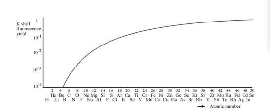
In a reflection geometry instrumentation, X-ray tube usually contains a side window made of Be to allow the generated X-rays to emit at the demanding angle. The reason that Be is used as a X-ray window, is that the fluorescence yield (ration between characteristic X ray and Auger emission) of Be is close to zero, so it can make sure the X-ray source is monochromatic and does not contain introduced chracteristic X-rays from other metals.
Sample Holder
There are many holder options to holder all kinds of samples and meet people’s requirement. Usually, evenly grinded sample powder is dissolved in organic solvent such as acetone or pressed into a plain on a glass slide to make sure the sampel is flat. The sample holder has a press ring to fix the slide. At low angles, the signal to noise ratio can be relatively larger and we can use a zero background sample holder to avoid that. It is usually made of single crystal silicon.
Detector
Photographic film serves as detector in earlier methods, Debye-Scherrer camera and Guinier camera methods2. The film is placed around the sample as a circle and records the diffracted X-ray beams. The positions of diffraction lines correspond to Bragg angle. And Photographic film can record both the reflected and transmitted X-ray beams. Nowadays, people tend to only select the reflected beam and use radiation counter as detector. Compared to film, scintillationcounter can measure diffraction intensities and Bragg angles more accurately. And it is very convenient use computer to analyze data.To prevent the X-ray beam from going though the sample, we need more powder sample.
Application
Phase Analysis
X-ray diffractometer is most widely used in the phase analysis because compare to other characterization method, XRD gives a fast and reliable measurement(measurement time is determined by the step size, angle range and the number of second per step) and easy sample preperation(well grinded powder). What people do after get their raw data is opening the data in a XRD data handling software (JADE, WinXPOW, ect.) and compare the raw data with the standard pattern in ICDD database. In many cases, the database may not contain the pattern of a specific compound you are working on, then you can easily generate a calculated pattern based on a crystal informtion file or the space group and lattice parameters. The diffraction pattern of a well-prepared sample should be very reliable (all the peaks should match the peaks in the reference pattern) and contains much information. When the sample has impurities, every kinds of substance will generate their own pattern independently and allows us to analysize seperately and help people control and optimize the reactions. Other factor that can influence the pattern may be the X-ray souce, sample crystallinity (smaller crystallinity can broaden the peaks), ect.
XRD technique is also capable for quantitative analysis of mixtures. The XRD data will not give the quantitative imformation because the intensity is not directly related to weight percantage. However, we can make a serie of controlled samples with different weight percentage of the impurity. Then XRD is performed on each of these sample and we can get a linear calibration curve which is the intensity ratio vs. weight percentage. The weight percentage in the sample can be determined based on the curve. If all the atomic and crystalline information are known, we can also conduct qualitative analysis with Rietveld method. A square least approximation method will be applied to modify all the parameters so that the difference between experimental point and the fitted pattern can be decreased to a least amount. During this process, the scale factor can also be determined. Rietveld method is widely used in samples containing more than one impurities.
Structure determination
Powder X-ray diffraction can not only be used to analyze phase information,but can also be used to determine the structure of unknown substances. However, since in powder XRD we can only get one-dimensional information rather than three-dimensional information, resolution in powder XRD is much lower than that from single crystal method and data refinement process is more sophisticated.“If representative single crystal method are available, then single crystal diffraction is the preferred method.”1
As shown in Figure 4.1, one Bragg Ring corresponds to a certain Miller plane. With the detected Bragg angle and equation 2.1, we can figure out the lattice parameters. The common method to manage data is direct method, Patterson method and Fourier method2. We can also use the square least approximation method, i.e. Rietveld method to refine the data, to refine the data and it has increased the resolution a lot.
Common single crystal methods are Laue method, four-circle diffractometer and rotating-crystal method.
Reference
- W. I. F. David, K. Shankland, L. B. McCusker, Ch. Baerlocher; Structure Determination from Powder Diffraction Data; Oxford; New York : Oxford University Press, 2002
- Anthony R. West; Basic Solid State Chemistry, Second Edition; New York : John Wiley & Sons, c1999
- Transimission Electron Microscope, Volume 1, David B. Williams, C. Barry Carter Springer,2009
- The Basics of Crystallography and Diffraction, Second Edition,Christopher Hammond;Oxford Science Publications, 2001
Problems
- Draw the lattice planes (1,1,1) (0,1,2) and (1,0,1) in a cubic lattice.
- If we use Cu αradiation as X-ray source, and the first order Bragg diffraction peak is found at the semi-angle 35。,calculate the d-spacing of the crystal.
- X-rays with wavelength 1.54 A are reflected from the (2,1,1) planes of a cubic crystal. The d-spacing is found to be 5.12A. Calculate the crystal parameter.
- Prove that for a body centered cubic lattice, reflection can be observed only when h+l+k=2n
- If you need to conduct powder XRD on an air sensitive crystal, choose a proper sample holder you need on line.