
pH Electrodes
- Page ID
- 78017

\( \newcommand{\vecs}[1]{\overset { \scriptstyle \rightharpoonup} {\mathbf{#1}} } \)
\( \newcommand{\vecd}[1]{\overset{-\!-\!\rightharpoonup}{\vphantom{a}\smash {#1}}} \)
\( \newcommand{\id}{\mathrm{id}}\) \( \newcommand{\Span}{\mathrm{span}}\)
( \newcommand{\kernel}{\mathrm{null}\,}\) \( \newcommand{\range}{\mathrm{range}\,}\)
\( \newcommand{\RealPart}{\mathrm{Re}}\) \( \newcommand{\ImaginaryPart}{\mathrm{Im}}\)
\( \newcommand{\Argument}{\mathrm{Arg}}\) \( \newcommand{\norm}[1]{\| #1 \|}\)
\( \newcommand{\inner}[2]{\langle #1, #2 \rangle}\)
\( \newcommand{\Span}{\mathrm{span}}\)
\( \newcommand{\id}{\mathrm{id}}\)
\( \newcommand{\Span}{\mathrm{span}}\)
\( \newcommand{\kernel}{\mathrm{null}\,}\)
\( \newcommand{\range}{\mathrm{range}\,}\)
\( \newcommand{\RealPart}{\mathrm{Re}}\)
\( \newcommand{\ImaginaryPart}{\mathrm{Im}}\)
\( \newcommand{\Argument}{\mathrm{Arg}}\)
\( \newcommand{\norm}[1]{\| #1 \|}\)
\( \newcommand{\inner}[2]{\langle #1, #2 \rangle}\)
\( \newcommand{\Span}{\mathrm{span}}\) \( \newcommand{\AA}{\unicode[.8,0]{x212B}}\)
\( \newcommand{\vectorA}[1]{\vec{#1}} % arrow\)
\( \newcommand{\vectorAt}[1]{\vec{\text{#1}}} % arrow\)
\( \newcommand{\vectorB}[1]{\overset { \scriptstyle \rightharpoonup} {\mathbf{#1}} } \)
\( \newcommand{\vectorC}[1]{\textbf{#1}} \)
\( \newcommand{\vectorD}[1]{\overrightarrow{#1}} \)
\( \newcommand{\vectorDt}[1]{\overrightarrow{\text{#1}}} \)
\( \newcommand{\vectE}[1]{\overset{-\!-\!\rightharpoonup}{\vphantom{a}\smash{\mathbf {#1}}}} \)
\( \newcommand{\vecs}[1]{\overset { \scriptstyle \rightharpoonup} {\mathbf{#1}} } \)
\( \newcommand{\vecd}[1]{\overset{-\!-\!\rightharpoonup}{\vphantom{a}\smash {#1}}} \)
\(\newcommand{\avec}{\mathbf a}\) \(\newcommand{\bvec}{\mathbf b}\) \(\newcommand{\cvec}{\mathbf c}\) \(\newcommand{\dvec}{\mathbf d}\) \(\newcommand{\dtil}{\widetilde{\mathbf d}}\) \(\newcommand{\evec}{\mathbf e}\) \(\newcommand{\fvec}{\mathbf f}\) \(\newcommand{\nvec}{\mathbf n}\) \(\newcommand{\pvec}{\mathbf p}\) \(\newcommand{\qvec}{\mathbf q}\) \(\newcommand{\svec}{\mathbf s}\) \(\newcommand{\tvec}{\mathbf t}\) \(\newcommand{\uvec}{\mathbf u}\) \(\newcommand{\vvec}{\mathbf v}\) \(\newcommand{\wvec}{\mathbf w}\) \(\newcommand{\xvec}{\mathbf x}\) \(\newcommand{\yvec}{\mathbf y}\) \(\newcommand{\zvec}{\mathbf z}\) \(\newcommand{\rvec}{\mathbf r}\) \(\newcommand{\mvec}{\mathbf m}\) \(\newcommand{\zerovec}{\mathbf 0}\) \(\newcommand{\onevec}{\mathbf 1}\) \(\newcommand{\real}{\mathbb R}\) \(\newcommand{\twovec}[2]{\left[\begin{array}{r}#1 \\ #2 \end{array}\right]}\) \(\newcommand{\ctwovec}[2]{\left[\begin{array}{c}#1 \\ #2 \end{array}\right]}\) \(\newcommand{\threevec}[3]{\left[\begin{array}{r}#1 \\ #2 \\ #3 \end{array}\right]}\) \(\newcommand{\cthreevec}[3]{\left[\begin{array}{c}#1 \\ #2 \\ #3 \end{array}\right]}\) \(\newcommand{\fourvec}[4]{\left[\begin{array}{r}#1 \\ #2 \\ #3 \\ #4 \end{array}\right]}\) \(\newcommand{\cfourvec}[4]{\left[\begin{array}{c}#1 \\ #2 \\ #3 \\ #4 \end{array}\right]}\) \(\newcommand{\fivevec}[5]{\left[\begin{array}{r}#1 \\ #2 \\ #3 \\ #4 \\ #5 \\ \end{array}\right]}\) \(\newcommand{\cfivevec}[5]{\left[\begin{array}{c}#1 \\ #2 \\ #3 \\ #4 \\ #5 \\ \end{array}\right]}\) \(\newcommand{\mattwo}[4]{\left[\begin{array}{rr}#1 \amp #2 \\ #3 \amp #4 \\ \end{array}\right]}\) \(\newcommand{\laspan}[1]{\text{Span}\{#1\}}\) \(\newcommand{\bcal}{\cal B}\) \(\newcommand{\ccal}{\cal C}\) \(\newcommand{\scal}{\cal S}\) \(\newcommand{\wcal}{\cal W}\) \(\newcommand{\ecal}{\cal E}\) \(\newcommand{\coords}[2]{\left\{#1\right\}_{#2}}\) \(\newcommand{\gray}[1]{\color{gray}{#1}}\) \(\newcommand{\lgray}[1]{\color{lightgray}{#1}}\) \(\newcommand{\rank}{\operatorname{rank}}\) \(\newcommand{\row}{\text{Row}}\) \(\newcommand{\col}{\text{Col}}\) \(\renewcommand{\row}{\text{Row}}\) \(\newcommand{\nul}{\text{Nul}}\) \(\newcommand{\var}{\text{Var}}\) \(\newcommand{\corr}{\text{corr}}\) \(\newcommand{\len}[1]{\left|#1\right|}\) \(\newcommand{\bbar}{\overline{\bvec}}\) \(\newcommand{\bhat}{\widehat{\bvec}}\) \(\newcommand{\bperp}{\bvec^\perp}\) \(\newcommand{\xhat}{\widehat{\xvec}}\) \(\newcommand{\vhat}{\widehat{\vvec}}\) \(\newcommand{\uhat}{\widehat{\uvec}}\) \(\newcommand{\what}{\widehat{\wvec}}\) \(\newcommand{\Sighat}{\widehat{\Sigma}}\) \(\newcommand{\lt}{<}\) \(\newcommand{\gt}{>}\) \(\newcommand{\amp}{&}\) \(\definecolor{fillinmathshade}{gray}{0.9}\)The most widely used ion-selective electrode is the glass pH electrode, which utilizes a thin glass membrane that is responsive to changes in H+ activity. F. Haber, in 1901, was the first person to observe that the voltage of a glass membrane changed with the acidity of a solution. In 1906, M. Cremer observed the pH dependence of measured potential across a thin glass membrane.
Today, pH sensitive glasses are manufactured primarily from SiO2 which are connected via a tetrahedral network with oxygen atoms bridging two silicon atoms (see an interactive 3d structure at http://www.geo.ucalgary.ca/~tmenard/...al/quartz.html). In addition, the glasses are made to contain varying amounts of other metal oxides, like Na2O and CaO. Oxygen atoms within the lattice that are not bound to two silicon atoms possess a negative charge, to which cations can ion pair. In this way, ions (primarily Na+) are able to diffuse slowly in the lattice, moving from one charge pair site to another. While the membrane resistance is very high (~100 MΩ), this movement of cations within the glass allows a potential to be measured across it.
If glasses of this type are placed in an aqueous solution containing H+, the glass surface in contact with solution becomes hydrated as water enters a short distance into the crystal lattice and causes it to swell. The “interior” of the glass remains dry. Some of the metal ions within the glass close to the solution boundary are able to diffuse into the solution, and some H+ ions are able to charge pair with oxygen near the glass surface. In this way, ion exchange equilibrium is established between the fixed negative sites on the glass surface and H+, with an increasing number of charge pairs with H+ occurring as its activity in the contacting solution increases. This equilibrium can be expressed by
\[\ce{H^{+/-}O-Si}- ⇔ \ce{H^+} + {^-\ce{O-Si}-}\]
where H+/-O-Si- and -O-Si- represent oxygen sites at the glass membrane ion paired with H+ and unpaired, respectively.
To function as a pH sensor, a layer of pH sensitive glass is placed between two solutions containing H+. As only the glass closest to solution becomes hydrated, two individual equilibria are established that are dependent upon the respective H+ activity on either side of the layer. This situation is illustrated below.
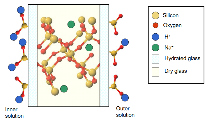
A difference in the H+ activities on either side of the glass membrane leads to a difference in the number of ion pairs that exist, and an imbalance in the surface charge between the hydrated layers. This results in a membrane potential that is pH dependent, described according to the Nernst equation
\[\mathrm{E_{membrane} = E_{inner} - E_{outer} = 0.0592 \log [(\mathcal{A}_{inner}) / (\mathcal{A}_{outer})]}\]
where Einner and Eouter are the surface potentials on either side of the membrane, and \(\mathcal{A_\mathrm{inner}}\) and \(\mathcal{A}_\mathrm{outer}\) represent the H+ activities of the inner and outer solutions, respectively.
Most commonly, pH electrodes are of a combination design, in which the glass membrane and the necessary reference electrodes are incorporated into the same electrode body. A figure of a typical combination pH electrode is shown below. (http://upload.wikimedia.org/wikipedi...ode_scheme.jpg)
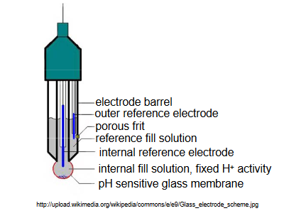
In this design, the inner fill solution contacting the glass membrane contains a fixed activity of H+. Typically, a Ag/AgCl reference electrode is in contact with this inner solution, and the solution contains 0.1 M HCl saturated with AgCl. A second Ag/AgCl reference electrode is located within a solution compartment surrounding the inner solution compartment. This solution is in contact with the external solution of unknown H+ activity through a porous frit on the side of the electrode barrel.
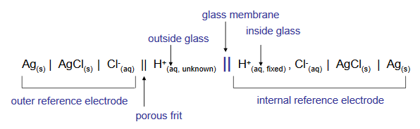
The combination electrode allows the measurement of both the inner and the outer membrane surface potentials, which as we saw above, is related to the solution pH by the Nernst equation. The theoretical potential across the glass membrane changes by 59.2 mV for each unit change in solution pH. A combination electrode cell can be represented by the shorthand notation below.
Practical considerations
The potential measured by a pH indicator electrode includes not only the desired membrane or boundary potential, but also small contributions from what are known as junction potentials and asymmetry potentials. Junction potential has been described in a separate section of this module, and for the specific case of the combination pH electrode is that which develops across the porous frit separating the second reference electrode from the external measured solution. Asymmetry potentials result from physical differences between the inner and outer surfaces of the glass membrane, leading to different inner and outer potentials for the same H+ activity. Corrections for these small potential errors can be made by frequent calibration of the glass electrode in standard solutions covering the pH range in which measurements are desired.
Users of glass pH electrodes should also be aware of alkaline and acid errors that limit the pH range over which effective measurements can be made. At very high pH, generally > 10, most glass electrodes become responsive to both H+ and Na+, with the measured pH being lower than actual. At low pH, typically < 1, glass membranes are susceptible to saturation by H+, and produce pH readings that are higher than actual. Specialty glasses are available that minimize these errors if routine measurements must be made at these pH extremes.
Solid state pH sensors
For many applications, such as those requiring ruggedness and miniaturization, a thin glass membrane is impractical as a pH sensor. Alternatives to the glass electrode include the ISFET, or ion selective field effect transistor. More information on solid state electrodes can be found at http://www.ph-meter.info/pH-electrode-solid-state, http://ieee-sensors.org/wp-content/u...T-Bergveld.pdf, and http://csrg.ch.pw.edu.pl/tutorials/isfet (accessed 7/28/2008).