6.3: Crystal Structure
- Page ID
- 83506
\( \newcommand{\vecs}[1]{\overset { \scriptstyle \rightharpoonup} {\mathbf{#1}} } \)
\( \newcommand{\vecd}[1]{\overset{-\!-\!\rightharpoonup}{\vphantom{a}\smash {#1}}} \)
\( \newcommand{\dsum}{\displaystyle\sum\limits} \)
\( \newcommand{\dint}{\displaystyle\int\limits} \)
\( \newcommand{\dlim}{\displaystyle\lim\limits} \)
\( \newcommand{\id}{\mathrm{id}}\) \( \newcommand{\Span}{\mathrm{span}}\)
( \newcommand{\kernel}{\mathrm{null}\,}\) \( \newcommand{\range}{\mathrm{range}\,}\)
\( \newcommand{\RealPart}{\mathrm{Re}}\) \( \newcommand{\ImaginaryPart}{\mathrm{Im}}\)
\( \newcommand{\Argument}{\mathrm{Arg}}\) \( \newcommand{\norm}[1]{\| #1 \|}\)
\( \newcommand{\inner}[2]{\langle #1, #2 \rangle}\)
\( \newcommand{\Span}{\mathrm{span}}\)
\( \newcommand{\id}{\mathrm{id}}\)
\( \newcommand{\Span}{\mathrm{span}}\)
\( \newcommand{\kernel}{\mathrm{null}\,}\)
\( \newcommand{\range}{\mathrm{range}\,}\)
\( \newcommand{\RealPart}{\mathrm{Re}}\)
\( \newcommand{\ImaginaryPart}{\mathrm{Im}}\)
\( \newcommand{\Argument}{\mathrm{Arg}}\)
\( \newcommand{\norm}[1]{\| #1 \|}\)
\( \newcommand{\inner}[2]{\langle #1, #2 \rangle}\)
\( \newcommand{\Span}{\mathrm{span}}\) \( \newcommand{\AA}{\unicode[.8,0]{x212B}}\)
\( \newcommand{\vectorA}[1]{\vec{#1}} % arrow\)
\( \newcommand{\vectorAt}[1]{\vec{\text{#1}}} % arrow\)
\( \newcommand{\vectorB}[1]{\overset { \scriptstyle \rightharpoonup} {\mathbf{#1}} } \)
\( \newcommand{\vectorC}[1]{\textbf{#1}} \)
\( \newcommand{\vectorD}[1]{\overrightarrow{#1}} \)
\( \newcommand{\vectorDt}[1]{\overrightarrow{\text{#1}}} \)
\( \newcommand{\vectE}[1]{\overset{-\!-\!\rightharpoonup}{\vphantom{a}\smash{\mathbf {#1}}}} \)
\( \newcommand{\vecs}[1]{\overset { \scriptstyle \rightharpoonup} {\mathbf{#1}} } \)
\(\newcommand{\longvect}{\overrightarrow}\)
\( \newcommand{\vecd}[1]{\overset{-\!-\!\rightharpoonup}{\vphantom{a}\smash {#1}}} \)
\(\newcommand{\avec}{\mathbf a}\) \(\newcommand{\bvec}{\mathbf b}\) \(\newcommand{\cvec}{\mathbf c}\) \(\newcommand{\dvec}{\mathbf d}\) \(\newcommand{\dtil}{\widetilde{\mathbf d}}\) \(\newcommand{\evec}{\mathbf e}\) \(\newcommand{\fvec}{\mathbf f}\) \(\newcommand{\nvec}{\mathbf n}\) \(\newcommand{\pvec}{\mathbf p}\) \(\newcommand{\qvec}{\mathbf q}\) \(\newcommand{\svec}{\mathbf s}\) \(\newcommand{\tvec}{\mathbf t}\) \(\newcommand{\uvec}{\mathbf u}\) \(\newcommand{\vvec}{\mathbf v}\) \(\newcommand{\wvec}{\mathbf w}\) \(\newcommand{\xvec}{\mathbf x}\) \(\newcommand{\yvec}{\mathbf y}\) \(\newcommand{\zvec}{\mathbf z}\) \(\newcommand{\rvec}{\mathbf r}\) \(\newcommand{\mvec}{\mathbf m}\) \(\newcommand{\zerovec}{\mathbf 0}\) \(\newcommand{\onevec}{\mathbf 1}\) \(\newcommand{\real}{\mathbb R}\) \(\newcommand{\twovec}[2]{\left[\begin{array}{r}#1 \\ #2 \end{array}\right]}\) \(\newcommand{\ctwovec}[2]{\left[\begin{array}{c}#1 \\ #2 \end{array}\right]}\) \(\newcommand{\threevec}[3]{\left[\begin{array}{r}#1 \\ #2 \\ #3 \end{array}\right]}\) \(\newcommand{\cthreevec}[3]{\left[\begin{array}{c}#1 \\ #2 \\ #3 \end{array}\right]}\) \(\newcommand{\fourvec}[4]{\left[\begin{array}{r}#1 \\ #2 \\ #3 \\ #4 \end{array}\right]}\) \(\newcommand{\cfourvec}[4]{\left[\begin{array}{c}#1 \\ #2 \\ #3 \\ #4 \end{array}\right]}\) \(\newcommand{\fivevec}[5]{\left[\begin{array}{r}#1 \\ #2 \\ #3 \\ #4 \\ #5 \\ \end{array}\right]}\) \(\newcommand{\cfivevec}[5]{\left[\begin{array}{c}#1 \\ #2 \\ #3 \\ #4 \\ #5 \\ \end{array}\right]}\) \(\newcommand{\mattwo}[4]{\left[\begin{array}{rr}#1 \amp #2 \\ #3 \amp #4 \\ \end{array}\right]}\) \(\newcommand{\laspan}[1]{\text{Span}\{#1\}}\) \(\newcommand{\bcal}{\cal B}\) \(\newcommand{\ccal}{\cal C}\) \(\newcommand{\scal}{\cal S}\) \(\newcommand{\wcal}{\cal W}\) \(\newcommand{\ecal}{\cal E}\) \(\newcommand{\coords}[2]{\left\{#1\right\}_{#2}}\) \(\newcommand{\gray}[1]{\color{gray}{#1}}\) \(\newcommand{\lgray}[1]{\color{lightgray}{#1}}\) \(\newcommand{\rank}{\operatorname{rank}}\) \(\newcommand{\row}{\text{Row}}\) \(\newcommand{\col}{\text{Col}}\) \(\renewcommand{\row}{\text{Row}}\) \(\newcommand{\nul}{\text{Nul}}\) \(\newcommand{\var}{\text{Var}}\) \(\newcommand{\corr}{\text{corr}}\) \(\newcommand{\len}[1]{\left|#1\right|}\) \(\newcommand{\bbar}{\overline{\bvec}}\) \(\newcommand{\bhat}{\widehat{\bvec}}\) \(\newcommand{\bperp}{\bvec^\perp}\) \(\newcommand{\xhat}{\widehat{\xvec}}\) \(\newcommand{\vhat}{\widehat{\vvec}}\) \(\newcommand{\uhat}{\widehat{\uvec}}\) \(\newcommand{\what}{\widehat{\wvec}}\) \(\newcommand{\Sighat}{\widehat{\Sigma}}\) \(\newcommand{\lt}{<}\) \(\newcommand{\gt}{>}\) \(\newcommand{\amp}{&}\) \(\definecolor{fillinmathshade}{gray}{0.9}\)There are three more structures, which are derived from close-packed lattices, that are particularly important because of the material properties of their compounds. These are the spinel structure, on which ferrites and other magnetic oxides are based, theperovskite structure, which is adopted by ferroelectric and superconducting oxides, and the rutile structure, which is a common binary 6:3 structure adopted by oxides and fluorides.
The spinel structure is formulated MM'2X4, where M and M' are tetrahedrally and octahedrally coordinated cations, respectively, and X is an anion (typically O or F). The structure is named after the mineral MgAl2O4, and oxide spinels have the general formula AB2O4.
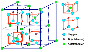
In the normal spinel structure, there is a close-packed array of anions. The A-site cations fill 1/8 of the tetrahedral holes and the B-site cations fill 1/2 of the octahedral holes.
Inverse spinels have a closely related structure (with the same large unit cell) in which the A-site ions and half of the B-site ions switch places. Inverse spinels are thus formulated B(AB)O4, where the AB ions in parentheses occupy octahedral sites, and the other B ions are on tetrahedral sites. There are also mixed spinels, which are intermediate between the normal and inverse spinel structure.
Some spinel and inverse spinel AB combinations are:
- A2+B3+, e.g., MgAl2O4 (normal spinel)
- A4+B2+, e.g., Pb3O4 = PbII(PbIIPbIV)O4 (inverse spinel)
- A6+B+, e.g., Na2WO4 (normal spinel)
Many magnetic oxides, such as Fe3O4 and CoFe2O4, are spinels.
Normal vs. inverse spinel structure
For transition metal oxide spinels, the choice of the normal vs. inverse spinel structure is driven primarily by the crystal field stabilization energy (CFSE) of ions in the tetrahedral and octahedral sites. For spinels that contain 3d elements such as Cr, Mn, Fe, Co, and Ni, the electron configuration is typically high spin because O2- is a weak field ligand.
As an example, we can consider magnetite, Fe3O4. This compound contains one Fe2+ and two Fe3+ ions per formula unit, so we could formulate it as a normal spinel, Fe2+(Fe3+)2O4, or as an inverse spinel, Fe3+(Fe2+Fe3+)O4. Which one would have the lowest energy?
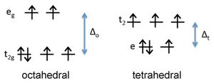
Figure: d-orbital energy diagram for \(Fe^{2+}\)
First we consider the crystal field energy of the Fe2+ ion, which is d6. Comparing the tetrahedral and high spin octahedral diagrams, we find that the CFSE in an octahedral field of O2- ions is [(4)(2/5) - (2)(3/5)]Δo - P = 0.4 Δo - P. In the tetrahedral field, the CFSE is [(3)(3/5) - (3)(2/5)]Δt - P = 0.6 Δt - P. Since Δo is about 2.25 times larger than Δt, the octahedral arrangement has a larger CFSE and is preferred for Fe2+.
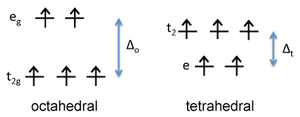
Figure : d-orbital energy diagram for \(Fe^{3+}\)
In contrast, it is easy to show that Fe3+, which is d5, would have a CFSE of zero in either the octahedral or tetrahedral geometry. This means that Fe2+ has a preference for the octahedral site, but Fe3+ has no preference. Consequently, we place Fe2+ on octahedral sites and Fe3O4 is an inverse spinel, Fe3+(Fe2+Fe3+)O4.Ferrites are compounds of general formula
MIIFe2O4. We can see that magnetite is one example of a ferrite (with M = Fe). Other divalent metals (M = Mg, Mn, Co, Ni, Zn) also form ferrites. Ferrites can be normal or inverse spinels, or mixed spinels, depending on the CFSE of the MII ion. Based on their CFSE, Fe2+, Co2+, and Ni2+ all have a strong preference for the octahedral site, so those compounds are all inverse spinels. ZnFe2O4 is a normal spinel because the small Zn2+ ion (d10) fits more easily into the tetrahedral site than Fe3+ (d5), and both ions have zero CFSE. MgFe2O4 and MnFe2O4, in which all ions have zero CFSE and no site preference, are mixed spinels. Chromite spinels, MIICr2O4, are always normal spinelsbecause the d3 Cr3+ ion has a strong preference for the octahedral site.
Figure: Illustration of antiferromagnetic superexchange between two transition metal cations through a shared oxygen atom.
Magnetism of ferrite spinels
Ferrite spinels are of technological interest because of their magnetic ordering, which can be ferrimagnetic or antiferromagnetic depending on the structure (normal or inverse) and the nature of the metal ions. Fe3O4, CoFe2O4, and NiFe2O4 are all inverse spinels and are ferrimagnets. The latter two compounds are used in magnetic recording media and as deflection magnets, respectively.
In order to understand the magnetism of ferrites, we need to think about how the unpaired spins of metal ions are coupled in oxides. If an oxide ion is shared by two metal ions, it can mediate the coupling of spins by superexchange as shown at the right. The coupling can be antiferromagnetic, as shown, or ferromagnetic, depending on the orbital filling and the symmetry of the orbitals involved. The Goodenough-Kanamori rules predict the local magnetic ordering (ferromagnetic vs. antiferromagnetic) that results from superexchange coupling of the electron spins of transition metal ions. For ferrites, the strongest coupling is between ions on neighboring tetrahedral and octahedral sites, and the ordering of spins between these two sites is reliably antiferromagnetic.
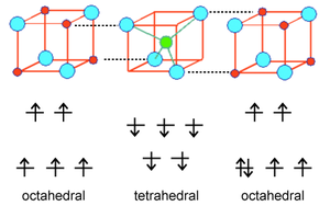
Because all the tetrahedral and octahedral sites in a spinel or inverse spinel crystal are coupled together identically, it works out that ions on the tetrahedral sites will all have one orientation (e.g., spin down) and ions on all the octahedral sites will have the opposite orientation (e.g., spin up). If the number of spins on the two sites is the same, then the solid will be antiferromagnetic. However, if the number of spins is unequal (as in the case of Fe3O4, CoFe2O4, and NiFe2O4) then the solid will be ferrimagnetic. This is illustrated above for Fe3O4. The spins on the Fe3+ sites cancel, because half of them are up and half are down. However, the four unpaired electrons on the Fe2+ ions are all aligned the same way in the crystal, so the compound is ferrimagnetic.
Perovskites are ternary oxides of general formula ABO3. More generally, the perovskite formula is ABX3, where the anion X can be O, N, or halogen. The A ions are typically large ions such as Sr2+, Ba2+, Rb+, or a lanthanide 3+ ion, and the B ions are smaller transition metal ions such as Ti4+, Nb5+, Ru4+, etc. The mineral after which the structure is named has the formula CaTiO3.
The perovskite structure has simple cubic symmetry, but is related to the fcc lattice in the sense that the A site cations and the three O atoms comprise a fcc lattice. The B-site cations fill 1/4 of the octahedral holes and are surrounded by six oxide anions.
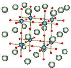
Figure: ABX3 perovskite structure. A, B, and X are white, blue, and red, respectively.
The coordination of the A ions in perovsite and the arrangement of BO6 octahedra is best understood by looking at the ReO3 structure, which is the same structure but with the A-site cations removed. In the polyhedral representation of the structure shown below, it can be seen that the octahedra share all their vertices but do not share any octahedral edges. This makes the ReO3 and perovskite structures flexible, like three-dimensional wine racks, in that the octahedra can rotate and tilt cooperatively. Eight such octahedra surround a large cuboctahedral cavity, which is the site of the A ions in the perovskite structure. Cations in these sites are coordinated by 12 oxide ions, as expected from the relationship between the perovskite and fcc lattices.
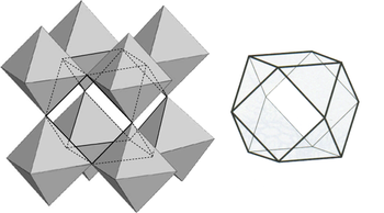
Figure: Polyhedral representation of the ReO3 structure showing the large cuboctahedral cavity that is surrounded by 12 oxygen atoms
Because the A-site is empty in the ReO3 structure, compounds with that structure can be reversibly intercalated by small ions such as Li+ or H+, which then occupy sites in the cuboctahedral cavity. For example, smart windows that darken in bright sunlight contain the electrochromic material WO3, which has the ReO3 structure. In the sunlight, a photovoltaic cell drives the reductive intercalation of WO3 according to the reaction:
\[x\mathrm{H^+} + x\mathrm{e^-} + {WO_3} \rightleftharpoons \ {H}_{x}\mathrm{WO_3}\]
WO3 is a light yellow compound containing d0 W(VI). In contrast, HxWO3, which is mixed-valent W(V)-W(VI) = d1-d0, has a deep blue color. Such coloration is typical of mixed-valence transition metal complexes because their d-electrons can be excited to delocalized conduction band levels by red light. Because the electrochemical intercalation-deintercalation process is powered by a solar cell, the tint of the windows can adjust automatically to the level of sunlight.
Ferroelectric perovskites
The flexibility of the network of corner-sharing BO6 octahedra is also very important in ferroelectric oxides that have the perovskite structure. In some perovsites with small B-site cations, such as Ti4+ and Nb5+, the cation is too small to fit symmetrically in the BO6 octahedron. The octahedron distorts, allowing the cation to move off-center. These distortions can be tetragonal (as in the figure shown below), rhombohedral, or orthorhombic, depending on whether the cation moves towards a vertex, face, or edge of the BO6 octahedron. Moving the cation off-center in the octahedron creates an electric dipole. In ferroelectrics, these dipoles align in neighboring unit cells through cooperative rotation and tilting of octahedra. The crystal thus acquires a net electrical polarization.
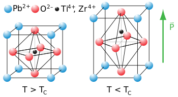
Figure: Tetragonal distortion of the perovskite unit cell in the ferroelectric oxide PZT, PbTixZr1-xO3
Ferroelectricity behaves analogously to ferromagnetism, except that the polarization is electrical rather than magnetic. In both cases, there is a critical temperature (Tc) above which the spontaneous polarization of the crystal disappears. Below Tc, the electric polarization of a ferroelectric can be switched with a coercive field, and hysteresis loop of polarization vs. field resembles that of a ferromagnet. Above Tc, the crystal is paraelectric and has a high dielectric permittivity.
Ferroelectric and paraelectric oxides (along with piezoelectrics and pyroelectrics) have a wide variety of applications as switches, actuators, transducers, and dielectrics for capacitors. Ferroelectric capacitors are important in memory devices (FRAM) and in the tuning circuits of cellular telephones. Multiferroics, which are materials that are simultaneously ferroelectric and ferromagnetic, are rare and are being now intensively researched because of their potential applications in electrically adressable magnetic memory.
Halide perovskites (ABX3, X = Cl, Br, I) can be made by combining salts of monovalent A ions (A+ = Cs+, NH4+, RNH3+) and divalent metal salts such as PbCl2 or PbI2. These compounds have sparked recent interest as light absorbers for thin film solar cells that produce electricity from sunlight. Lead and tin halide perovskites can be grown as thin films from solution precursors or by thermal evaporation at relatively low temperatures. In some lead halide perovskites, the mobility of electrons and holes is very high, comparable to that of more expensive III-V semiconductors such as GaAs, which must be grown as very pure single crystals at high temperatures for use in solar cells. Because of their high carrier mobility, some lead halide perovskites are also electroluminescent and are of interest as inexpensive materials for light-emitting diodes (LEDs).
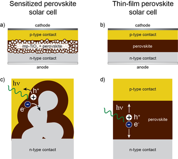
Figure: a) Solar cell architecture in which a lead halide perovskite absorber coats a layer of nanocrystalline anatase TiO2. b) Thin-film solar cell, with a layer of lead halide perovskite sandwiched between two selective contacts. c) Charge generation and extraction in the sensitized architecture and d) in the thin-film architecture.
Tin and lead halide perovskites were first studied in the 1990s as materials for thin film electronics, and more recently as light absorbers in dye-sensitized solar cells. Soon after the results on dye-sensitized perovskite cells were reported, it was discovered that halide perovskites could also be used in thin film solid state solar cells. The structures of these solar cells are shown schematically at the right. The highest reported solar power conversion efficiencies of perovskite solar cells have jumped from 3.8% in 2009 to 10.2% in 2012 and a certified 20.1% in 2014. The highest performing cells to date contain divalent lead in the perovskite B cation site and a mixture of methylammonium and formamidinium ions in the perovskite A cation site.
Despite their very impressive efficiency, perovskite solar cells are stable for relatively short periods of time and are sensitive to air and moisture. Current research is focused on understanding the degradation mechanisms of these solar cells and improving their stability under operating conditions.
The rutile structure is an important MX2 (X = O, F) structure. It is a 6:3 structure, in which the cations are octahedrally coordinated by anions, and as such is intermediate in polarity between the CaF2 (8:4) and SiO2 (4:2) structures. The mineral rutile is one of the polymorphs of TiO2, the others (anatase and brookite) also being 6:3 structures.
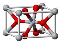
Figure: Rutile crystal lattice
The rutile structure can be described as a distorted version of the NiAs structure with half the cations removed. Recall that compounds with the NiAs structure were typically metallic because the metal ions are eclipsed along the stacking axis and thus are in relatively close contact. In rutile, the MO6 octahedra share edges along the tetragonal c-axis, and so some rutile oxides, such as NbO2, RuO2 and IrO2, are also metallic because of d-orbital overlap along that axis. These compounds are important as electrolyzer catalysts and catalyst supports because they combine high catalytic activity with good electronic conductivity.
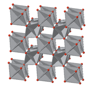
Figure: View down the tetragonal c-axis of the rutile lattice, showing edge-sharing MO6octahedra.
Rutile TiO2, because of its high refractive index, is the base pigment for white paint. It is a wide bandgap semiconductor that has also been extensively researched as an electrode for water splitting solar cells and as a photocatalyst (primarily as the anatase polymorph) for degradation of pollutants in air and water. Self-cleaning glass exploits the photocatalytic properties of a thin film of TiO2 to remove oily substances from the glass surface and improve the wetting properties of the glass.
Contributors
Adapted from the Wikibook constructed by Chemistry 310 students at Penn State University.

