
2.4A: Macroscale Columns
- Page ID
- 93526

\( \newcommand{\vecs}[1]{\overset { \scriptstyle \rightharpoonup} {\mathbf{#1}} } \)
\( \newcommand{\vecd}[1]{\overset{-\!-\!\rightharpoonup}{\vphantom{a}\smash {#1}}} \)
\( \newcommand{\id}{\mathrm{id}}\) \( \newcommand{\Span}{\mathrm{span}}\)
( \newcommand{\kernel}{\mathrm{null}\,}\) \( \newcommand{\range}{\mathrm{range}\,}\)
\( \newcommand{\RealPart}{\mathrm{Re}}\) \( \newcommand{\ImaginaryPart}{\mathrm{Im}}\)
\( \newcommand{\Argument}{\mathrm{Arg}}\) \( \newcommand{\norm}[1]{\| #1 \|}\)
\( \newcommand{\inner}[2]{\langle #1, #2 \rangle}\)
\( \newcommand{\Span}{\mathrm{span}}\)
\( \newcommand{\id}{\mathrm{id}}\)
\( \newcommand{\Span}{\mathrm{span}}\)
\( \newcommand{\kernel}{\mathrm{null}\,}\)
\( \newcommand{\range}{\mathrm{range}\,}\)
\( \newcommand{\RealPart}{\mathrm{Re}}\)
\( \newcommand{\ImaginaryPart}{\mathrm{Im}}\)
\( \newcommand{\Argument}{\mathrm{Arg}}\)
\( \newcommand{\norm}[1]{\| #1 \|}\)
\( \newcommand{\inner}[2]{\langle #1, #2 \rangle}\)
\( \newcommand{\Span}{\mathrm{span}}\) \( \newcommand{\AA}{\unicode[.8,0]{x212B}}\)
\( \newcommand{\vectorA}[1]{\vec{#1}} % arrow\)
\( \newcommand{\vectorAt}[1]{\vec{\text{#1}}} % arrow\)
\( \newcommand{\vectorB}[1]{\overset { \scriptstyle \rightharpoonup} {\mathbf{#1}} } \)
\( \newcommand{\vectorC}[1]{\textbf{#1}} \)
\( \newcommand{\vectorD}[1]{\overrightarrow{#1}} \)
\( \newcommand{\vectorDt}[1]{\overrightarrow{\text{#1}}} \)
\( \newcommand{\vectE}[1]{\overset{-\!-\!\rightharpoonup}{\vphantom{a}\smash{\mathbf {#1}}}} \)
\( \newcommand{\vecs}[1]{\overset { \scriptstyle \rightharpoonup} {\mathbf{#1}} } \)
\( \newcommand{\vecd}[1]{\overset{-\!-\!\rightharpoonup}{\vphantom{a}\smash {#1}}} \)
\(\newcommand{\avec}{\mathbf a}\) \(\newcommand{\bvec}{\mathbf b}\) \(\newcommand{\cvec}{\mathbf c}\) \(\newcommand{\dvec}{\mathbf d}\) \(\newcommand{\dtil}{\widetilde{\mathbf d}}\) \(\newcommand{\evec}{\mathbf e}\) \(\newcommand{\fvec}{\mathbf f}\) \(\newcommand{\nvec}{\mathbf n}\) \(\newcommand{\pvec}{\mathbf p}\) \(\newcommand{\qvec}{\mathbf q}\) \(\newcommand{\svec}{\mathbf s}\) \(\newcommand{\tvec}{\mathbf t}\) \(\newcommand{\uvec}{\mathbf u}\) \(\newcommand{\vvec}{\mathbf v}\) \(\newcommand{\wvec}{\mathbf w}\) \(\newcommand{\xvec}{\mathbf x}\) \(\newcommand{\yvec}{\mathbf y}\) \(\newcommand{\zvec}{\mathbf z}\) \(\newcommand{\rvec}{\mathbf r}\) \(\newcommand{\mvec}{\mathbf m}\) \(\newcommand{\zerovec}{\mathbf 0}\) \(\newcommand{\onevec}{\mathbf 1}\) \(\newcommand{\real}{\mathbb R}\) \(\newcommand{\twovec}[2]{\left[\begin{array}{r}#1 \\ #2 \end{array}\right]}\) \(\newcommand{\ctwovec}[2]{\left[\begin{array}{c}#1 \\ #2 \end{array}\right]}\) \(\newcommand{\threevec}[3]{\left[\begin{array}{r}#1 \\ #2 \\ #3 \end{array}\right]}\) \(\newcommand{\cthreevec}[3]{\left[\begin{array}{c}#1 \\ #2 \\ #3 \end{array}\right]}\) \(\newcommand{\fourvec}[4]{\left[\begin{array}{r}#1 \\ #2 \\ #3 \\ #4 \end{array}\right]}\) \(\newcommand{\cfourvec}[4]{\left[\begin{array}{c}#1 \\ #2 \\ #3 \\ #4 \end{array}\right]}\) \(\newcommand{\fivevec}[5]{\left[\begin{array}{r}#1 \\ #2 \\ #3 \\ #4 \\ #5 \\ \end{array}\right]}\) \(\newcommand{\cfivevec}[5]{\left[\begin{array}{c}#1 \\ #2 \\ #3 \\ #4 \\ #5 \\ \end{array}\right]}\) \(\newcommand{\mattwo}[4]{\left[\begin{array}{rr}#1 \amp #2 \\ #3 \amp #4 \\ \end{array}\right]}\) \(\newcommand{\laspan}[1]{\text{Span}\{#1\}}\) \(\newcommand{\bcal}{\cal B}\) \(\newcommand{\ccal}{\cal C}\) \(\newcommand{\scal}{\cal S}\) \(\newcommand{\wcal}{\cal W}\) \(\newcommand{\ecal}{\cal E}\) \(\newcommand{\coords}[2]{\left\{#1\right\}_{#2}}\) \(\newcommand{\gray}[1]{\color{gray}{#1}}\) \(\newcommand{\lgray}[1]{\color{lightgray}{#1}}\) \(\newcommand{\rank}{\operatorname{rank}}\) \(\newcommand{\row}{\text{Row}}\) \(\newcommand{\col}{\text{Col}}\) \(\renewcommand{\row}{\text{Row}}\) \(\newcommand{\nul}{\text{Nul}}\) \(\newcommand{\var}{\text{Var}}\) \(\newcommand{\corr}{\text{corr}}\) \(\newcommand{\len}[1]{\left|#1\right|}\) \(\newcommand{\bbar}{\overline{\bvec}}\) \(\newcommand{\bhat}{\widehat{\bvec}}\) \(\newcommand{\bperp}{\bvec^\perp}\) \(\newcommand{\xhat}{\widehat{\xvec}}\) \(\newcommand{\vhat}{\widehat{\vvec}}\) \(\newcommand{\uhat}{\widehat{\uvec}}\) \(\newcommand{\what}{\widehat{\wvec}}\) \(\newcommand{\Sighat}{\widehat{\Sigma}}\) \(\newcommand{\lt}{<}\) \(\newcommand{\gt}{>}\) \(\newcommand{\amp}{&}\) \(\definecolor{fillinmathshade}{gray}{0.9}\)Procedural Generalities
The same underlying principles of thin layer chromatography (TLC) apply to column chromatography. In fact, a TLC is always run before performing a column to assess the situation and determine the proper solvent ratio. In order to get good separation, it is ideal if the desired component has an \(R_f\) around 0.35 and is separated from other components by at least 0.2 \(R_f\) units.\(^8\) If the spots to be separated are very close (if the difference in \(R_f\) is < 0.2), it's best if the middle of the spots has an \(R_f\) of 0.35. An \(R_f\) near 0.35 is ideal because it is slow enough that stationary-mobile phase equilibration can occur, but fast enough to minimize band widening from diffusion.
There are a few variables which aren't applicable to TLC, but which affect the separation of components in column chromatography. These include the column diameter, quantity of adsorbent used, and solvent flow rate. Table 2.5 summarizes variable recommendations based on the sample size and degree of separation between components. In all scenarios, the columns are to be prepped between 5-6 inches high.
| Column diameter (mm) | Volume of eluent (mL) | Sample size (mg) If \(\Delta R_f\) > 0.2 |
Sample size (mg) If \(\Delta R_f\) > 0.1 |
Typical fraction size (mL) |
|---|---|---|---|---|
| 10 | 100 | 100 | 40 | 5 |
| 20 | 200 | 400 | 160 | 10 |
| 30 | 400 | 900 | 360 | 20 |
| 40 | 600 | 1600 | "600 | 30 |
For example, a column of one-inch diameter (\(1 \: \text{in}\) is \(25.4 \: \text{mm}\)) should be able to purify around \(400 \: \text{mg}\) of material if the separation is good (\(\Delta R_f\) > 0.2, third column in Table 2.5), or around \(160 \: \text{mg}\) if the separation is difficult (\(\Delta R_f\) > 0.1). The column should be able to be prepared and eluted using around \(200 \: \text{mL}\) of solvent, and the fractions can be collected with approximately \(10 \: \text{mL}\) of solution each.\(^9\)
There are multiple variations on how to physically run a column, and your instructor may prefer a certain method. One large difference in methods is how the column is prepared. In the "dry packing" method, dry silica or alumina is added directly to a column, and solvent is allowed to trickle through in portions, then with pressure. In the "wet packing" method, the column is filled with solvent first, then dry silica or alumina is lightly shaken in, then packed with pressure. In the "slurry" method, solvent is added to the silica or alumina in an Erlenmeyer flask, poured onto the column as a sludgy material, then packed with pressure.
It is important to know that heat is liberated when solvent is added to silica or alumina (they have an exothermic heat of solvation). The slurry method is presented in this section, with the main reason being that it allows this exothermic step to happen in an Erlenmeyer flask instead of on the column. If heat is liberated during the packing of the column, it may generate bubbles from the boiling of solvent. These can interfere with the separation of the column if they are not adequately removed, and can crack the adsorbent material in the column.
Step-by-Step Procedures
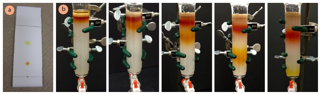
The column pictured in this section shows purification of a \(0.20 \: \text{g}\) sample containing a mixture of ferrocene and acetylferrocene (crude TLC is in Figure 2.51a). Roughly \(8 \: \text{mL}\) fractions were collected into small test tubes, and roughly \(400 \: \text{mL}\) of eluent was used.
Run a TLC
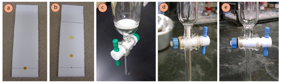
- Run a TLC of the sample to be purified (Figures 2.52 a+b) to determine the appropriate solvent for chromatography. The desired component should have an \(R_f\) around 0.35 and should ideally be separated from all other spots by at least 0.2 \(R_f\) units.
- Prepare a batch of eluent that gives the proper \(R_f\) value. The quantity prepared depends on the quantity of sample, the size of the column, and whether or not the solvent composition is planned to be changed midway. (See Table 2.5 for guidelines and the eluotropic series for trends in "solvent power.")
Prepare the packed column
- Obtain an appropriate column (see Table 2.5), and be sure there is something near the stopcock that will allow liquid to pass through, but not solid. Columns may have a sintered disk (also known as a "frit," Figure 2.52c), or a plug of cotton or glass wool remaining from the previous user (Figure 2.52d). If no disk or plug is present (Figure 2.52e), wedge a small wad of cotton or glass wool into the bottom of the column using a long rod.
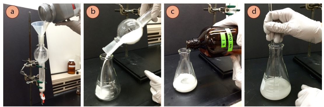
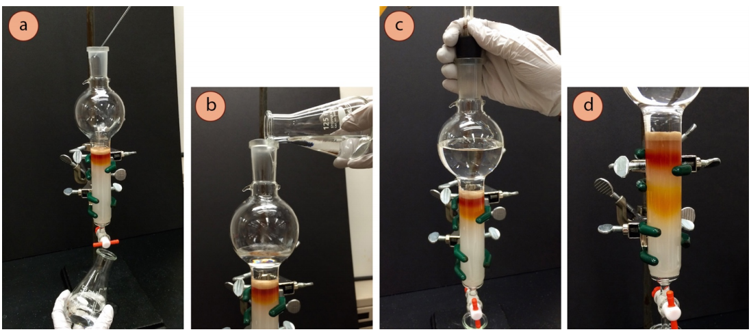
- Secure your column perfectly vertically to a ring stand or latticework, clamping it with three-fingered clamps in two locations. In the fume hood, pour silica gel or alumina adsorbent into the column to between 5-6 inches high (Figure 2.53a).
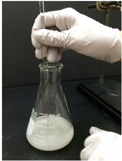
Safety note: Powdered silica and alumina are lung irritants, and should always be handled carefully in a fume hood. Spilled dust should be disposed of by mopping it with a wet paper towel (if wet, the fine particles are less dispersive). - In the fume hood, pour the adsorbent measured in the column into an Erlenmeyer flask (Figure 2.53b), then add some eluent (Figure 2.53c). Make a loose slurry by swirling and stirring with a glass stirring rod (Figure 2.53d) until all of the adsorbent is completely wet, gas bubbles are released, and the consistency is somewhat thick but pourable.

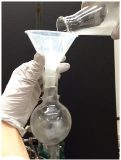
- Put a beaker or Erlenmeyer flask beneath the clamped column and open the stopcock. In one quick motion, swirl and pour the silica or alumina slurry into the column using a large-mouthed funnel (Figure 2.54a). Immediately use more eluent to rinse residual slurry out of the Erlenmeyer flask (Figure 2.54b) and onto the column.
- Immediately rinse any silica or alumina off the sides of the column reservoir using eluent and a swirling motion from a Pasteur pipette (Figures 2.54 c+d). If allowed to dry, the adsorbent will cling to the glass and won't easily be rinsed down.
- Jostle the column firmly using a cork ring or your knuckles (Figure 2.55a) to dislodge any air bubbles in the column (which could cause poor separation or cracking of the adsorbent in the column), and to promote an even deposition of adsorbent.
- Apply gentle air pressure to the top of the column (Figure 2.55b) to compress it, stopping when the eluent level is \(1 \: \text{cm}\) from the top of the column. If a T-adapter is used with the air line as in Figure 2.55b, fine control of the airflow can be accomplished by adjustment of the pinch clamp on the rubber tubing.
Throughout the entire elution process, keep the white column of adsorbent wet, with the eluent level above the top of the silica or alumina.
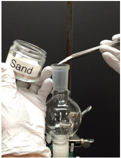
Gently break the seal to cease application of pressure, and close the stopcock to prevent liquid from dripping out further. - Add a thin layer of sand (Figure 2.55c), approximately \(0.5 \: \text{cm}\) high. Rinse the sides of the column with eluent using a swirling motion to dislodge the sand off the sides of the glass (Figure 2.55d). Open the stopcock and allow liquid to drip out until the liquid is just above the sand layer. Apply air pressure if the dripping is too slow.
Add the sample
Once the sample is applied to the column, there is a race against time, as diffusion will start to broaden the material. A sample should not be applied until you are ready to complete the column immediately and in its entirety. This process may take between 15 and 90 minutes! If using test tubes to collect fractions, the test tubes should be arranged in a rack prior to adding the sample, and the column height should be adjusted so that the test tube rack can slide underneath.
- If the crude sample is a liquid, use it directly (go on to step 13).
- If the crude sample is a solid, do one of the following things:
- Ideal situation: dissolve the solid in the minimum amount of the eluent (a few \(\text{mL}\) at most).
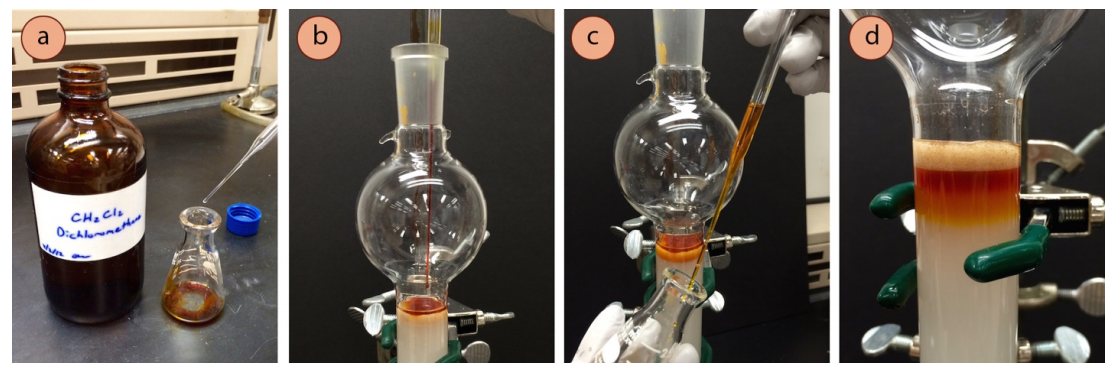
- If the solid is not particularly soluble, or will not dissolve in a few \(\text{mL}\) of the eluent, dissolve it in the minimum amount of dichloromethane (few \(\text{mL}\) at most, Figure 2.56a).
- If the solid is insoluble in the eluent, an alternate procedure is also possible. Dissolve the solid in a round-bottomed flask using a few \(\text{mL}\) of a low-boiling solvent (e.g. dichloromethane or acetone). Add to the flask approximately \(1 \: \text{g}\) of silica or alumina, then remove the solvent on the rotary evaporator in order to leave a solid that contains the sample deposited on the adsorbent. With an inch of eluent resting atop the packed column (skip adding the sand layer if this method is used), pour the silica-adsorbed sample onto the column using a wide mouthed funnel. If any dust clings to the glass, rinse it down with more eluent (go on to step 15.)
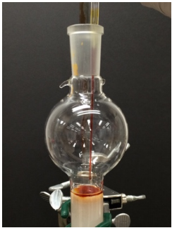
- Delicately add the sample to the column via pipette, dripping the liquid or solution directly onto the sand with the pipette tip as close as you can manage, not down the sides (Figure 2.56b). Take care to not squirt liquid in forcibly such that indentations would be caused in the sand or silica /alumina column.
- Rinse the sample container with a little solvent (or dichloromethane if used, Figure 2.56c) and add the rinsing to the column using the same pipette (in order to rinse the pipette as well).
- Open the stopcock and allow liquid to drip out until the sample is just past the sand layer (Figure 2.56d) and into the white area of the column (apply air pressure if this takes more than 20 seconds).
- Gently rinse the sides of the column with a swirling motion using 1-2 pipettes-full of eluent to rinse any splashed sample. Again, allow liquid to drip out (or apply air pressure) until the sample is pushed into the white adsorbent.
Repeat the rinsing step until you feel confident that the entire sample is deposited on the adsorbent. If some of the sample is still located in the sand layer, it may dissolve in the eluent when more solvent is added, leading to a loss of yield. If the compound is colored, the rinsing should be completely clear.
Fill with Eluent and Elute the Column
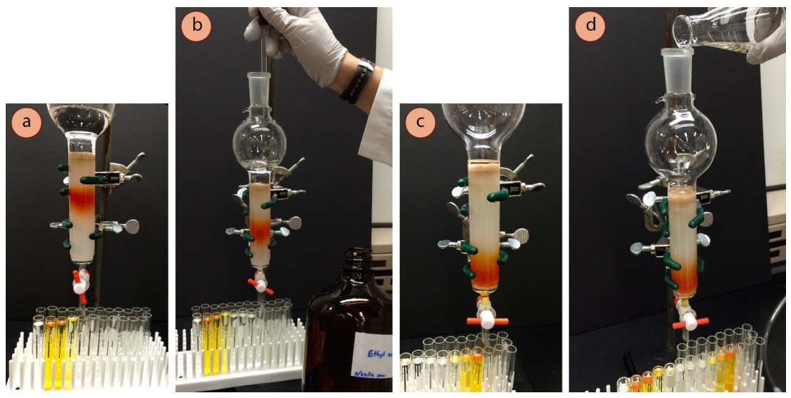
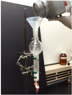
- Delicately add more eluent via pipette (Figure 2.57a), swirling down the sides, and then when the sand layer would no longer be disturbed with the additions, carefully pour in larger quantities (Figure 2.57b) of the prepared eluent to fill the reservoir (or fill with as much as may be needed). Clean eluent collected during the packing of the column can be reused.
- Use air pressure to gently and steadily elute the sample through the column (Figures 2.57 c+d). The more times the pressure is started and stopped, the more likely the column may crack. It's best if the pressure can be kept gentle and steady the entire time.
The optimal drip rate during elution depends on the size of the column. The ideal flow of eluent is when the solvent in the cylindrical section of the column above the adsorbent drops at a rate of 2.0 inches per minute.\(^{10}\) Therefore, the drip rate should be slower with a narrow column compared to a wider column.
The drip rate for a one-inch column should be where individual drops can be barely distinguished. A stream of liquid pouring out the stopcock with this size of column is slightly too fast.
Collect fractions
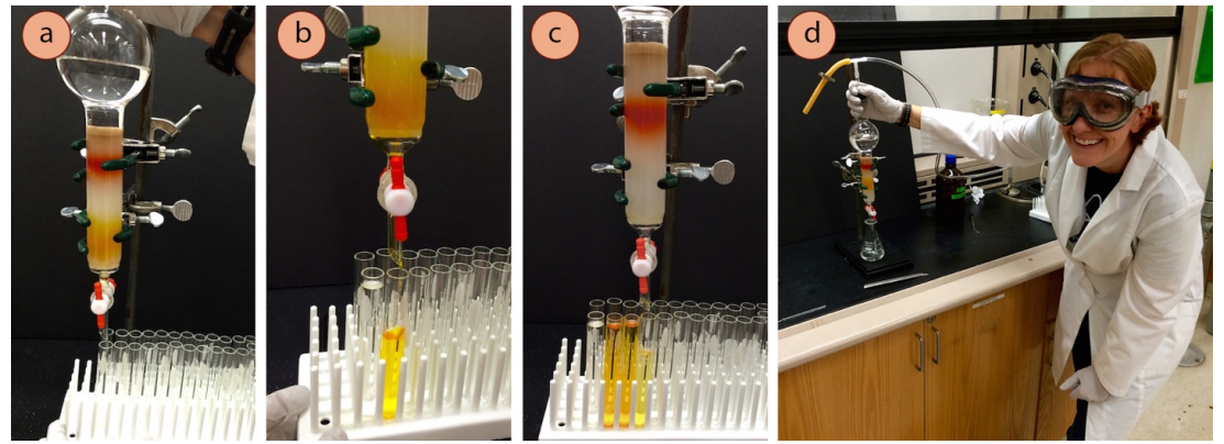
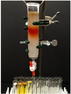
- Immediately start collecting the eluting liquid into test tubes on a rack (Figure 2.58a). See Table 2.5 for recommendations on volumes to collect in each test tube.
- When the first test tube fills, or if a certain height of liquid has been collected as recommended by your instructor or Table 2.5, move the rack over to start collecting into a different tube (Figures 2.58 b+c). Fill and keep the tubes in order on the rack.
These different tubes are called "fractions". The goal of a column is to collect small enough fractions that most (or some) fractions contain pure material. If the separation of the mixture is difficult (if the \(\Delta R_f\) of the components is low), it may be best to collect small fractions (e.g. half-filled tubes).
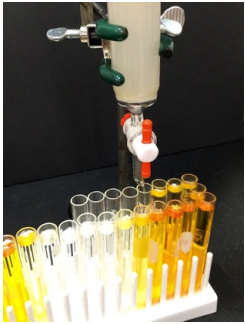
- As liquid drains off the column, it often splashes onto the outsides of the tip of the column, and when the solvent evaporates you may see a ring of material on the tip (you will see a ring of solid if the component is a solid as in Figure 2.59b, or oily droplets if the component is a liquid). If the components are colored, the column tip should be rinsed (Figure 2.59c) when it appears as if one component has completely eluted and before the other component approaches.
- Periodically keep an eye on the eluent level, and refill before it drops below the sand layer.
Possibly Increase the Solvent Polarity
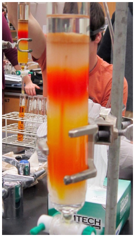
- One eluent may be used throughout the entire column, especially if the components to be separated have similar \(R_f\) values. However, if the components have very different \(R_f\) values, the solvent polarity may be increased after one component has eluted from the column (Figure 2.60a).
Increasing the solvent polarity will make components travel "faster." There are several reasons a faster elution is desired. First, if one component has already exited the column, the column has already done its job with separation, so speeding up the process will not affect the purity of the collected fractions. Second, the longer it takes to run a column, the wider will be the component bands (due to diffusion), and collecting a broad band of material will use (and waste) a lot of solvent.
Table 2.6 contains a partial list of the eluotropic series, a list of common solvents ranked according to their "solvent power" in normal phase chromatography. The more polar solvent causes the most dramatic increase in \(R_f\).
| Eluotropic Series (from least to most polar) |
|---|
| Petroleum ether / hexanes |
| Dichloromethane |
| Diethyl ether |
| Ethyl acetate |
| Acetone |
| Methanol |
- To increase the solvent polarity, the polar solvent can be dripped directly into the eluent on the column reservoir (Figure 2.60b). For example, if using a hexanes:ethyl acetate mixture, addition of pure ethyl acetate to the eluent currently in the reservoir would increase its polarity. If the eluent level is running low, a solution could be prepared that contains a higher percentage of the more polar component. For example, if the column first used a 4:1 hexanes:ethyl acetate mixture, using a 1:1 mixture would be a more polar solvent.
- Elute the column with the more polar solvent as before, and always remember to watch the eluent level, and refill (Figure 2.60d) before it drops below the sand layer.
Find and Concentrate the Desired Component
- In finding the desired component in the test tube fractions, it is helpful to understand the relationship between \(R_f\) and elution order in column chromatography.
In column chromatography, the sample is deposited on the top of the column and eluted down, while in thin layer chromatography the sample is spotted on the bottom of the plate and eluted up. Therefore, a column can be thought of like an upside-down TLC plate. A compound with a higher \(R_f\) runs "faster," meaning it will end up higher on a TLC plate, and will be collected first with a column.
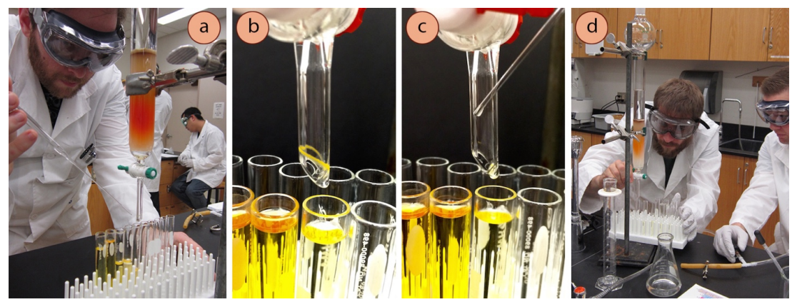
In the column pictured in this section, the component with the lower \(R_f\) (orange on the TLC plate in Figure 2.61a), is the component collected second from the column. - First determine which test tubes contain dissolved compound.
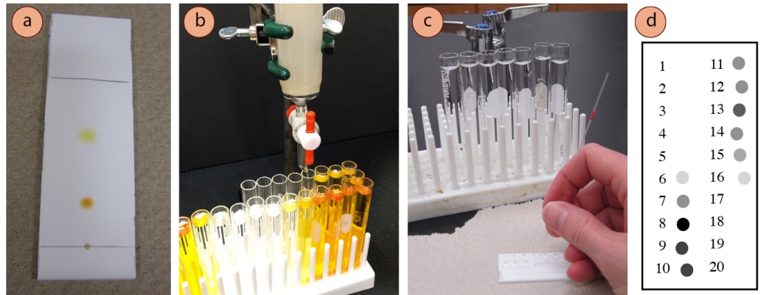
- Spot a sample of each fraction on a TLC plate labeled with fraction numbers corresponding to the order in which they were collected (Figure 2.61c). It may be best to spot each sample 2-3 times over top of one another in case the fractions are dilute.
- If many fractions have been collected, making you hesitant to sample every fraction, one method to identify colorless fractions that may contain compound is to look for a hint of residue on the top of the test tubes. After evaporation, a solid residue (Figure 2.62) or oily droplets are sometimes left on the top of the test tube, making obvious that those fractions contain more than just solvent. Sample all fractions near the tubes containing visible residue.

- Visualize the spotted TLC plate using UV light and/or a stain to determine which fractions contain compound (Figure 2.61d).
- Run a TLC of all fractions that contain compound, spotting up to five samples per 1-inch wide TLC plate. Wider TLC plates may be used for this purpose if available.
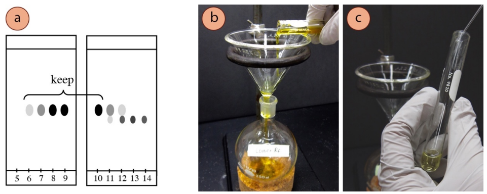
- Identify the compound with the desired \(R_f\) by comparison with the original crude TLC plate. Choose to retain the fractions that have the desired compound in pure form, as evidenced by the eluted TLC plate. For example, if the compound with the higher \(R_f\) is desired in Figure 2.63a, fractions 6-10 should be kept.
- Combine the pure fractions into an appropriately sized round-bottomed flask (no more than half-full, Figure 2.63b). Rinse each test tube with a small amount of eluent (or other solvent if solubility is an issue), and add the rinsing to the round-bottomed flask (Figure 2.63c).
- Evaporate the solvent on the rotary evaporator to leave the purified compound in the flask.
Clean Up the Column
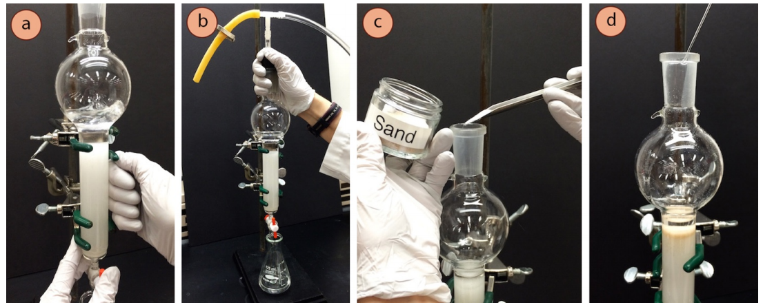
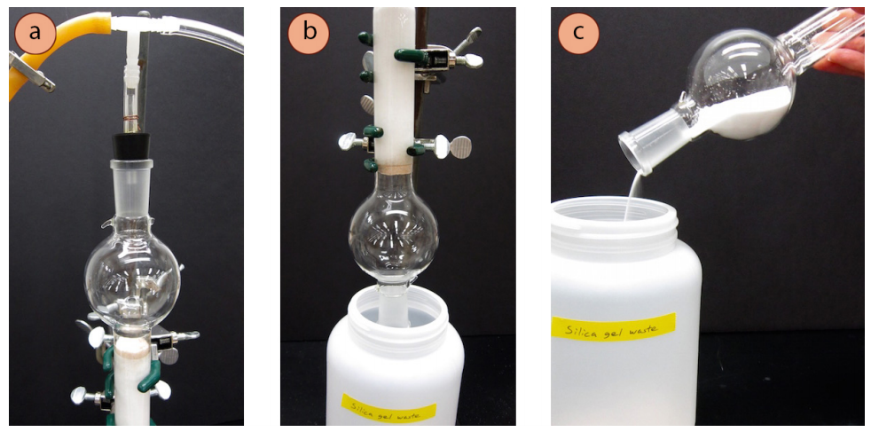
- To dry the column, apply air pressure to drain the majority of eluent from the column into a waste container. Then further dry the column using one of these methods:
- Leave connected a gentle stream of air running through the column to further dry it as you clean up other things (Figure 2.64a).
- Clamp the column upside down over a large waste beaker in the fume hood, so that the adsorbent will fall when it has dried (Figure 2.64b). This will take a long time (until the next class period), but is an option.
- When dry, the adsorbent can be poured out of the column into a waste container in the fume hood (Figure 2.64c).
Safety note: Powdered adsorbents are a lung irritant, and their hazard is exacerbated if the column contains residual compounds that can now make their way into your lungs. Pouring silica or alumina powders should always be done in the fume hood. - When the majority of the adsorbent has been collected in a waste container, use water to rinse any residual solid into the sink, and then rinse the column with acetone into a waste beaker. Further clean the column with soap and water and dry with the stopcock parts separated.
Macroscale Column Summary
 |
 |
 |
 |
|
Make sure there is a frit or cotton plug in the bottom of the column. Fill the column with silica or alumina to 5-6 inches in the fume hood. |
Pour the adsorbent into an Erlenmeyer flask and add eluent to make a pourable slurry. The eluent should give the desired component an \(R_f\) of 0.35 by TLC. |
Pour in the slurry and immediately rinse the sides of the column with eluent and a pipette. Jostle the column to remove air bubbles. Use air pressure to pack the column. Keep it perfectly vertical. |
Add \(0.5 \: \text{cm}\) of sand. Rinse the sand off the sides carefully with a swirling motion. Don't disrupt the top surface of the silica or alumina with rinsing. |
 |
 |
 |
 |
|
Adjust the eluent level to the sand layer, and then add the sample (pure liquid, dissolved in \(\ce{CH_2Cl_2}\), or solid adsorbed onto a portion of silica). Rinse the sides and use air pressure to force the eluent down onto the silica/alumina layer. |
Fill the reservoir with eluent (carefully to not disrupt the top surface). Use steady air pressure to elute the column. Collect fractions in test tubes in a rack (keep in order). |
Rinse the column tip if a component has finished coming off the column. Possibly increase the eluent polarity to make components elute faster. Never allow the eluent to drop below the top of the adsorbent column. |
Use TLC to determine the purity of the fractions, and combine appropriate fractions. Remove the solvent with the rotary evaporator. |
Troubleshooting
The Pipette Broke in the Column
It is quite common to break the tip of a Pasteur pipette while rinsing the column, which often falls and wedges itself into the delicate column. Unfortunately, a broken pipette in a column can cause problems with the separation of components.
For example, Figure 2.65 shows the effect of a broken pipette on the separation of two components. A broken pipette is embedded in the column and is the nearly vertical line of orange seen between the two bands on the column. Since stationary-mobile phase equilibration does not occur on the glass surface of the pipette, compounds stream down quickly and move faster than they should based on their \(R_f\). The orange vertical line is the top component draining into the band of the bottom component, contaminating it.
If a broken pipette pierces the column, and the sand or sample has not yet been applied, attempt to remove the pipette with long forceps. After removal, vigorously jostle the column to pack it again and continue on with the column. If the pipette cannot be removed with forceps, you may consider redoing the column.
If the sand has already been applied, removal of the pipette and jostling the column will often ruin the horizontal surface of the adsorbent, so it will be necessary to re-pack the column.
If the sample has already been applied, there isn't anything to do but continue on and hope for the best. If the column results in an unsuccessful separation, all fractions containing the compound of interest can be combined, solvent evaporated by the rotary evaporator, and another purification method (or a second column) can be attempted.
Air Bubbles are Seen in the Column
Like a broken pipette, an air bubble is an empty pocket where stationary-mobile phase equilibration does not happen, so components move quicker around an air bubble than they should. This may lead to uneven eluting bands, which can cause overlap if the separation of the mixture is difficult (if the components have very close \(R_f\) values, as in Figure 2.66).
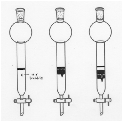
If air bubbles are seen in the column and the sand or sample has not yet been applied, give the column a good jostling during packing to remove all air bubbles. See your instructor if the bubbles are not budging as you may be approaching the task too delicately. If the sand or sample has already been applied, it's best to leave the column as is and hope the air bubbles do not affect the separation.
The Bands are Eluting Unevenly
If the components of a mixture are colored, it may be obvious when the bands elute in a crooked manner. This is most likely due to the column being clamped at a slight diagonal.
If the column is clamped in a slanted manner, components will travel in a slanted manner (Figure 2.67). This may cause separation problems if the components have a similar \(R_f\).

There is no way to fix this problem midway through a column, but if the components have very different \(R_f\) values, the slanted bands may have no effect on the separation. In the future, be sure to check that the column is perfectly vertical in both the side-to-side and front-back directions.
\(^8\)W.C. Still, M. Kahn, A. Mitra, J. Org. Chem., Vol. 43, No. 14, 1978.
\(^9\)A typical small test tube \(\left( 13 x 100 \: \text{mm} \right)\) has a capacity of \(9 \: \text{mL}\), and a typical medium test tube \(\left( 18 x 150 \: \text{mm} \right)\) has a capacity of \(27 \: \text{mL}\).
\(^{10}\)W.C. Still, M. Kahn, A. Mitra, J. Org. Chem., Vol. 43, No. 14, 1978.