The gas flow system
- Page ID
- 61147
\( \newcommand{\vecs}[1]{\overset { \scriptstyle \rightharpoonup} {\mathbf{#1}} } \)
\( \newcommand{\vecd}[1]{\overset{-\!-\!\rightharpoonup}{\vphantom{a}\smash {#1}}} \)
\( \newcommand{\id}{\mathrm{id}}\) \( \newcommand{\Span}{\mathrm{span}}\)
( \newcommand{\kernel}{\mathrm{null}\,}\) \( \newcommand{\range}{\mathrm{range}\,}\)
\( \newcommand{\RealPart}{\mathrm{Re}}\) \( \newcommand{\ImaginaryPart}{\mathrm{Im}}\)
\( \newcommand{\Argument}{\mathrm{Arg}}\) \( \newcommand{\norm}[1]{\| #1 \|}\)
\( \newcommand{\inner}[2]{\langle #1, #2 \rangle}\)
\( \newcommand{\Span}{\mathrm{span}}\)
\( \newcommand{\id}{\mathrm{id}}\)
\( \newcommand{\Span}{\mathrm{span}}\)
\( \newcommand{\kernel}{\mathrm{null}\,}\)
\( \newcommand{\range}{\mathrm{range}\,}\)
\( \newcommand{\RealPart}{\mathrm{Re}}\)
\( \newcommand{\ImaginaryPart}{\mathrm{Im}}\)
\( \newcommand{\Argument}{\mathrm{Arg}}\)
\( \newcommand{\norm}[1]{\| #1 \|}\)
\( \newcommand{\inner}[2]{\langle #1, #2 \rangle}\)
\( \newcommand{\Span}{\mathrm{span}}\) \( \newcommand{\AA}{\unicode[.8,0]{x212B}}\)
\( \newcommand{\vectorA}[1]{\vec{#1}} % arrow\)
\( \newcommand{\vectorAt}[1]{\vec{\text{#1}}} % arrow\)
\( \newcommand{\vectorB}[1]{\overset { \scriptstyle \rightharpoonup} {\mathbf{#1}} } \)
\( \newcommand{\vectorC}[1]{\textbf{#1}} \)
\( \newcommand{\vectorD}[1]{\overrightarrow{#1}} \)
\( \newcommand{\vectorDt}[1]{\overrightarrow{\text{#1}}} \)
\( \newcommand{\vectE}[1]{\overset{-\!-\!\rightharpoonup}{\vphantom{a}\smash{\mathbf {#1}}}} \)
\( \newcommand{\vecs}[1]{\overset { \scriptstyle \rightharpoonup} {\mathbf{#1}} } \)
\( \newcommand{\vecd}[1]{\overset{-\!-\!\rightharpoonup}{\vphantom{a}\smash {#1}}} \)
\(\newcommand{\avec}{\mathbf a}\) \(\newcommand{\bvec}{\mathbf b}\) \(\newcommand{\cvec}{\mathbf c}\) \(\newcommand{\dvec}{\mathbf d}\) \(\newcommand{\dtil}{\widetilde{\mathbf d}}\) \(\newcommand{\evec}{\mathbf e}\) \(\newcommand{\fvec}{\mathbf f}\) \(\newcommand{\nvec}{\mathbf n}\) \(\newcommand{\pvec}{\mathbf p}\) \(\newcommand{\qvec}{\mathbf q}\) \(\newcommand{\svec}{\mathbf s}\) \(\newcommand{\tvec}{\mathbf t}\) \(\newcommand{\uvec}{\mathbf u}\) \(\newcommand{\vvec}{\mathbf v}\) \(\newcommand{\wvec}{\mathbf w}\) \(\newcommand{\xvec}{\mathbf x}\) \(\newcommand{\yvec}{\mathbf y}\) \(\newcommand{\zvec}{\mathbf z}\) \(\newcommand{\rvec}{\mathbf r}\) \(\newcommand{\mvec}{\mathbf m}\) \(\newcommand{\zerovec}{\mathbf 0}\) \(\newcommand{\onevec}{\mathbf 1}\) \(\newcommand{\real}{\mathbb R}\) \(\newcommand{\twovec}[2]{\left[\begin{array}{r}#1 \\ #2 \end{array}\right]}\) \(\newcommand{\ctwovec}[2]{\left[\begin{array}{c}#1 \\ #2 \end{array}\right]}\) \(\newcommand{\threevec}[3]{\left[\begin{array}{r}#1 \\ #2 \\ #3 \end{array}\right]}\) \(\newcommand{\cthreevec}[3]{\left[\begin{array}{c}#1 \\ #2 \\ #3 \end{array}\right]}\) \(\newcommand{\fourvec}[4]{\left[\begin{array}{r}#1 \\ #2 \\ #3 \\ #4 \end{array}\right]}\) \(\newcommand{\cfourvec}[4]{\left[\begin{array}{c}#1 \\ #2 \\ #3 \\ #4 \end{array}\right]}\) \(\newcommand{\fivevec}[5]{\left[\begin{array}{r}#1 \\ #2 \\ #3 \\ #4 \\ #5 \\ \end{array}\right]}\) \(\newcommand{\cfivevec}[5]{\left[\begin{array}{c}#1 \\ #2 \\ #3 \\ #4 \\ #5 \\ \end{array}\right]}\) \(\newcommand{\mattwo}[4]{\left[\begin{array}{rr}#1 \amp #2 \\ #3 \amp #4 \\ \end{array}\right]}\) \(\newcommand{\laspan}[1]{\text{Span}\{#1\}}\) \(\newcommand{\bcal}{\cal B}\) \(\newcommand{\ccal}{\cal C}\) \(\newcommand{\scal}{\cal S}\) \(\newcommand{\wcal}{\cal W}\) \(\newcommand{\ecal}{\cal E}\) \(\newcommand{\coords}[2]{\left\{#1\right\}_{#2}}\) \(\newcommand{\gray}[1]{\color{gray}{#1}}\) \(\newcommand{\lgray}[1]{\color{lightgray}{#1}}\) \(\newcommand{\rank}{\operatorname{rank}}\) \(\newcommand{\row}{\text{Row}}\) \(\newcommand{\col}{\text{Col}}\) \(\renewcommand{\row}{\text{Row}}\) \(\newcommand{\nul}{\text{Nul}}\) \(\newcommand{\var}{\text{Var}}\) \(\newcommand{\corr}{\text{corr}}\) \(\newcommand{\len}[1]{\left|#1\right|}\) \(\newcommand{\bbar}{\overline{\bvec}}\) \(\newcommand{\bhat}{\widehat{\bvec}}\) \(\newcommand{\bperp}{\bvec^\perp}\) \(\newcommand{\xhat}{\widehat{\xvec}}\) \(\newcommand{\vhat}{\widehat{\vvec}}\) \(\newcommand{\uhat}{\widehat{\uvec}}\) \(\newcommand{\what}{\widehat{\wvec}}\) \(\newcommand{\Sighat}{\widehat{\Sigma}}\) \(\newcommand{\lt}{<}\) \(\newcommand{\gt}{>}\) \(\newcommand{\amp}{&}\) \(\definecolor{fillinmathshade}{gray}{0.9}\)The gas flow system consists of the following components:
- Gas cylinder(s) or generator
- Pressure reducers and manometer
- Gas filter(s)
- Tubing
- (Mass) flow controller
- Pressure regulator
- (Needle valve)
- Injector
- Column
- Detector
The design of the entire gas system from various manufacturers is basically the same for all GC apparatus. The components of a carrier gas system are discussed in the following paragraphs. The individual components are either directly connected or by means of a length of tubing. Detector gas systems are, with the exception of the injector and the column, comparable to carrier gas systems. There is a direct connection between flow controller/pressure regulator and the detector.
Gas Supply
Carrier gas can be supplied by:
- Gas cylinders: The majority of gases are obtained from cylinders that deliver pressures up to 200 bar. Each cylinder is labeled and painted in a particular color to identify the gas it contains. Gas cylinders are required, in view of the high primary pressure, to be equipped with a pressure reducing valve. This valve is fitted with two metal pressure gauges and two pressure chambers. The valve maintains a constant secondary gas pressure in the GC system as long as there is sufficient primary pressure.
- Gas generators: In addition to cylinders, generators can also be used for carrier gas supply.
The three most common gas generators are:
- Nitrogen generator: The nitrogen generator separates nitrogen and argon by means of a molecular sieve (Molsieve) from the other components in air.
- Hydrogen generator: The hydrogen generator can also be employed in combination with the air generator as gas supply for flame ionization detectors. Hydrogen is generated by electrolysis of distilled water and is suitable for use after drying.
- Air generator: The air generator compresses air and purifies it from dust and water. In contrast to cylinders, which have an unlimited supply capacity if there is enough pressure, the generators have a limited capacity.
The first two generators supply carrier gas, which has similar purity as from cylinders.
| Limitation of Generators | |||
| Generator | Max. capacity (ml/min) | Objective | Max. number of GCs |
| nitrogen | 300 | carrier for packed GC |
4
|
| hydrogen | 225 | carrier for packed GC | 2 |
| hydrogen | 225 | flame ionization detector | 6 |
| air | 1800 | flame ionization detector | 6 |
Gas filters
When working at high sensitivities, the demands on the purity of gases are high. Impure gases cause extra noise and affect column lifetimes. Decline of the column lifetime and noise can be avoided by installing filters in the gas supply lines before introducing the carrier gas into the chromatographic system.
In practice the following filters are being used:
For carrier gases
- Moisture filters to remove water and sometimes traces of oil from connections or pressure gauges
- Oxygen filters to remove oxygen and traces of sulphur and chlorine compounds
For detector-fuel gases
- Active charcoal filters to remove organic compounds
The filters in the carrier gas supply line should be installed in a particular order: first the moisture filter and then the oxygen filter. If the filters are placed in reverse order, the stationary phase can be destroyed by oxygen, which was dissolved in the water and released after filtering.
Tubings
The best materials for tubing are copper and stainless steel. Not on account of their pressure resistance, but due to their impermeability to gases.
For carrier gas lines:
- Copper
- Stainless steel
For air pressure supply only:
- Polyamide (nylon)
- PTFE (Teflon)
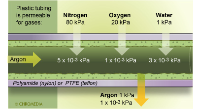
Completely gas-tight thermoplastic synthetic materials do not exist and plastic tubing is permeable to gases, such as helium. Carrier gas,as well as detector gases, can diffuse through the tubing wall. But in view of the small amounts and the fact that this usually happens in the gas flow system before pressure or flow regulation, it will not present any difficulties. Problems, hoewever, may be encountered with oxygen entering the tubing wall via diffusion.
Tubing in GC
When oxygen or organic contaminants come into contact with the stationary phase, this will have severe consequences on the retention times, the peak shape and on the detector signal (including the baseline). Metal tubing does not present these problems.
Fittings
All fittings are compression-type fittings:
- Gas cylinder connections with a flat or convex compression type fitting (seal)
- Column connections with a conical fitting (ferrules)
Fittings
When using gas cylinders it is important to make sure that the seal (a flat o-ring) has the correct diameter and thickness and that the seal is made of the correct material. The most commonly used materials are Teflon and thermo-hard elastomers such as Buna-S.
Some particular designs of cylinders do not have a seals due to the use of a leak tight metal-to-metal construction.
The gas system is usually connected to the gas chromatograph by means of a 1/16" or 1/8" female nut (depending on the line thickness) with a ferrule. Always use the appropriate type of nut and ferrule compatible with the type of GC flow system.
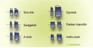
The thread, the angle of the ferrule cone that creates the seal, the shape and length of the ferrule and the insert length of the fittings vary widely from one manufacturer to another. Therefore interchange might cause serious difficulties.
The connection of a metal packed column is made the same way as the connection of tubing to the gas chromatograph.
Compression fitting with two-piece ferrule design
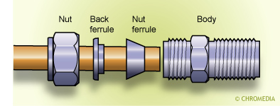
Compression type fittings can be used more than once, provided that the ferrule is not deformed too much and that the thread of the nut is not damaged. Make sure that the material of the ferrule is always as soft as, or softer than, the material of the nut and the tubing.
A compression fitting creates a seal due to the slight deformation of the ferrule. In order to create a good leak-tight connection it is essential to use the proper fittings and to have a burr-free, squared off tubing end. In this case it is sufficient to hand-tighten the nut in the fitting and afterwards to tighten it further for 3/4 of a turn with a good fitting spanner.
| Different Types of Ferrules | |||
| Material | Max.temp (celcius) | Re-use | Bleeding |
| Graphite | 400 | Yes/no | no |
| Vespel | 350 | yes | minor |
| (Kalrez) | 310 | yes | ? |
| Teflon | 250 | no | yes |
Once a ferrule is connected it usually needs only a 1/4 extra turn. In all cases the following rule applies:
TIGHT IS TIGHT
Do not exert too much force; a stripped nut will result in a leaking connection. After applying gas pressure, check if the connections are leak-tight.
The outside and inside dimensions of packed column ferrules are defined in inches. The size of the inner diameter of a ferrule determines its suitability for a tube with the same inch size. For example, a ferrule with the dimensions 1/8" x 1/16" can be used for a 1/8" nut and a 1/16" tube.
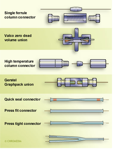
GC-capillary connection systems