
7. Pressure Assembly
- Page ID
- 62446

\( \newcommand{\vecs}[1]{\overset { \scriptstyle \rightharpoonup} {\mathbf{#1}} } \)
\( \newcommand{\vecd}[1]{\overset{-\!-\!\rightharpoonup}{\vphantom{a}\smash {#1}}} \)
\( \newcommand{\id}{\mathrm{id}}\) \( \newcommand{\Span}{\mathrm{span}}\)
( \newcommand{\kernel}{\mathrm{null}\,}\) \( \newcommand{\range}{\mathrm{range}\,}\)
\( \newcommand{\RealPart}{\mathrm{Re}}\) \( \newcommand{\ImaginaryPart}{\mathrm{Im}}\)
\( \newcommand{\Argument}{\mathrm{Arg}}\) \( \newcommand{\norm}[1]{\| #1 \|}\)
\( \newcommand{\inner}[2]{\langle #1, #2 \rangle}\)
\( \newcommand{\Span}{\mathrm{span}}\)
\( \newcommand{\id}{\mathrm{id}}\)
\( \newcommand{\Span}{\mathrm{span}}\)
\( \newcommand{\kernel}{\mathrm{null}\,}\)
\( \newcommand{\range}{\mathrm{range}\,}\)
\( \newcommand{\RealPart}{\mathrm{Re}}\)
\( \newcommand{\ImaginaryPart}{\mathrm{Im}}\)
\( \newcommand{\Argument}{\mathrm{Arg}}\)
\( \newcommand{\norm}[1]{\| #1 \|}\)
\( \newcommand{\inner}[2]{\langle #1, #2 \rangle}\)
\( \newcommand{\Span}{\mathrm{span}}\) \( \newcommand{\AA}{\unicode[.8,0]{x212B}}\)
\( \newcommand{\vectorA}[1]{\vec{#1}} % arrow\)
\( \newcommand{\vectorAt}[1]{\vec{\text{#1}}} % arrow\)
\( \newcommand{\vectorB}[1]{\overset { \scriptstyle \rightharpoonup} {\mathbf{#1}} } \)
\( \newcommand{\vectorC}[1]{\textbf{#1}} \)
\( \newcommand{\vectorD}[1]{\overrightarrow{#1}} \)
\( \newcommand{\vectorDt}[1]{\overrightarrow{\text{#1}}} \)
\( \newcommand{\vectE}[1]{\overset{-\!-\!\rightharpoonup}{\vphantom{a}\smash{\mathbf {#1}}}} \)
\( \newcommand{\vecs}[1]{\overset { \scriptstyle \rightharpoonup} {\mathbf{#1}} } \)
\( \newcommand{\vecd}[1]{\overset{-\!-\!\rightharpoonup}{\vphantom{a}\smash {#1}}} \)
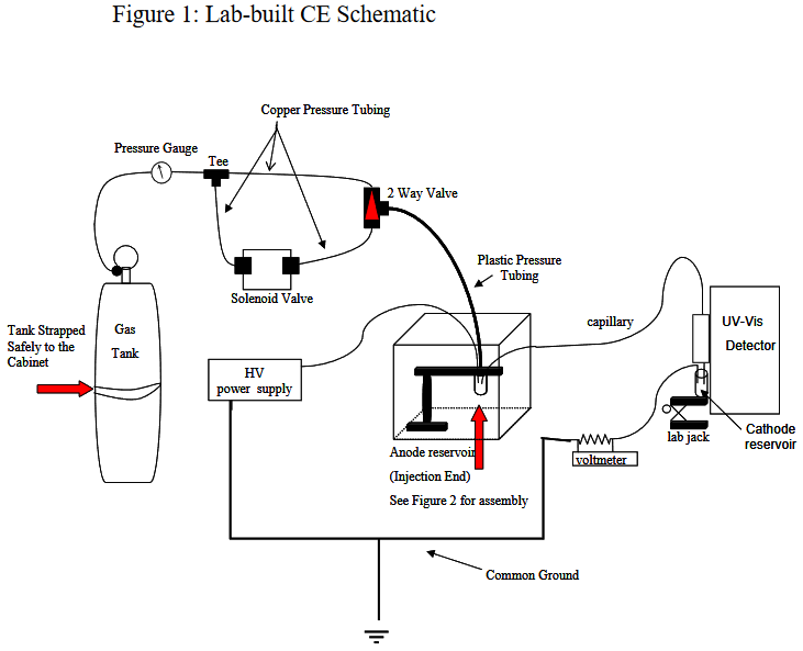
See the Custom Built CE Schematic for a diagram.
This section describes the assembly of the pressure injection system (See Custom-built CE Schematic) used to introduce sample plugs into the bare-fused silica capillary. It is important to note that copper and Teflon tubing should be installed and used according to the manufacturer’s specifications and recommendations.
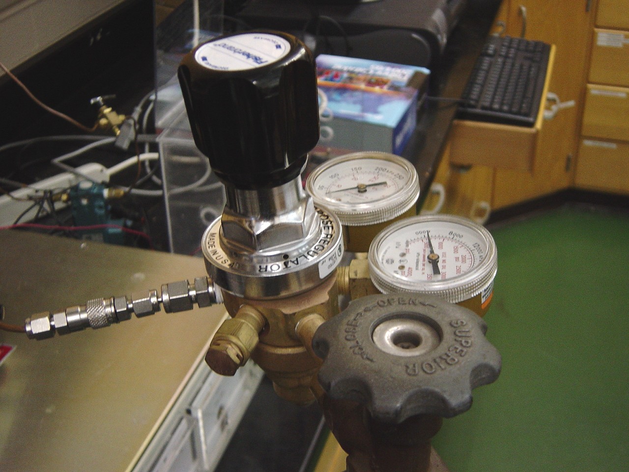
- A tank of compressed helium should be strapped safely to the cabinet. A pressure regulator should already be connected to the gas tank.

Pressure Regulator.
- Copper tubing should connect the pressure regulator to the pressure valve using a quick connector.
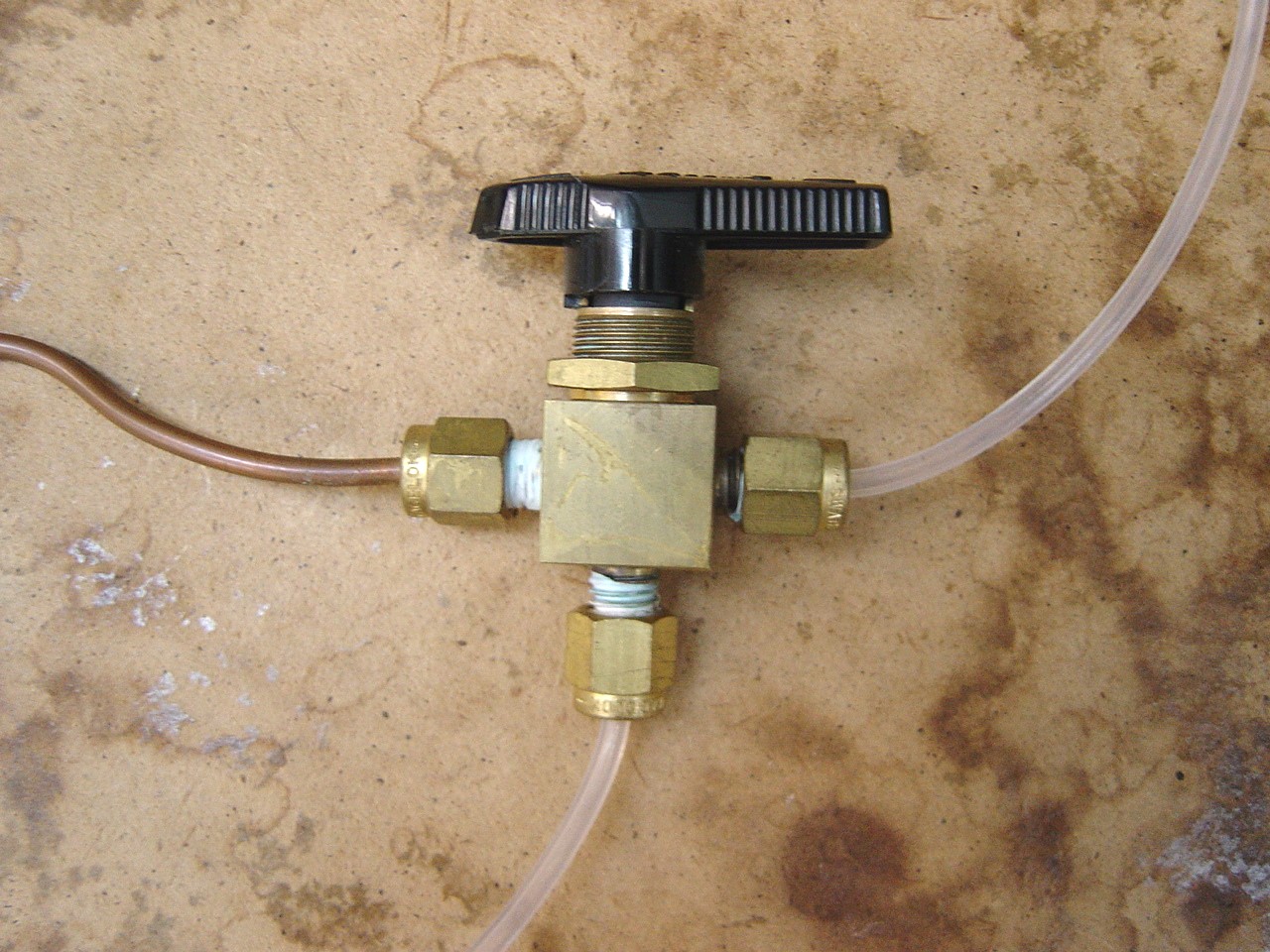
- The pressure valve is then connected to a 1/8” union T.
- The union T is then connected to the 3-way valve by copper tubing. The 3-way valve controls the flow of pressure to the sample vial (“ON/OFF” switch).
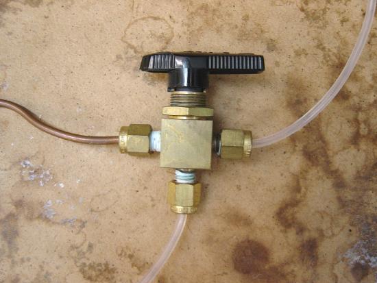
Three-Way Valve.
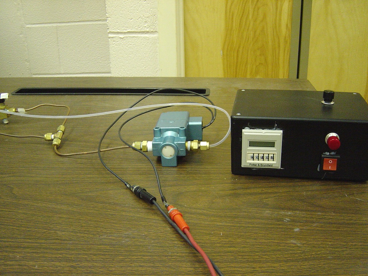
- The 3-way valve is then connected to the solenoid valve by copper tubing.
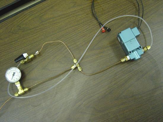
Bottom: Pressure Assembly
- The black and red wires from the Solenoid valve connect to an electronic timer.
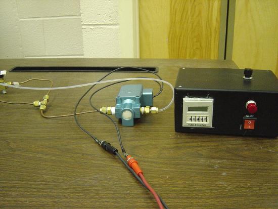
Pressure Assembly and Timer
- The solenoid valve is then connected back to the union T by copper tubing.
- The 3-way valve also connects to the plastic pressure tubing. The pressure tubing should go through a hole in the plexi-glass box and pierce the septa and be placed right above the sample. The plastic tubing SHOULD NOT be submerged in the sample.
