
5.1: Crystal Structures and Unit Cells
- Page ID
- 326183
Introduction
The term "closest packed structures" refers to the most tightly packed or space-efficient composition of crystal structures (lattices). Imagine an atom in a crystal lattice as a sphere. While cubes may easily be stacked to fill up all empty space, unfilled space will always exist in the packing of spheres. To maximize the efficiency of packing and minimize the volume of unfilled space, the spheres must be arranged as close as possible to each other. These arrangements are called closest packed structures. The packing of spheres can describe the solid structures of crystals. In a crystal structure, the centers of atoms, ions, or molecules lie on the lattice points. Atoms are assumed to be spherical to explain the bonding and structures of metallic crystals. These spherical particles can be packed into different arrangements. In closest packed structures, the arrangement of the spheres are densely packed in order to take up the greatest amount of space possible.
Close-Packing of Identical Spheres
Crystals are of course three-dimensional objects, but we will begin by exploring the properties of arrays in two-dimensional space. This will make it easier to develop some of the basic ideas without the added complication of getting you to visualize in 3-D — something that often requires a bit of practice. Suppose you have a dozen or so marbles. How can you arrange them in a single compact layer on a table top? Obviously, they must be in contact with each other in order to minimize the area they cover. It turns out that there are two efficient ways of achieving this:
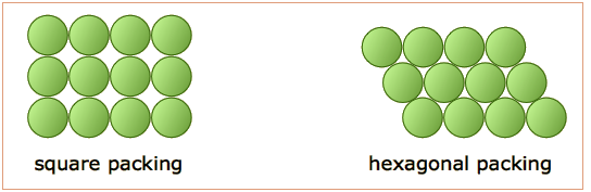
The essential difference here is that any marble within the interior of the square-packed array is in contact with four other marbles, while this number rises to six in the hexagonal-packed arrangement. It should also be apparent that the latter scheme covers a smaller area (contains less empty space) and is therefore a more efficient packing arrangement. If you are good at geometry, you can show that square packing covers 78 percent of the area, while hexagonal packing yields 91 percent coverage.
If we go from the world of marbles to that of atoms, which kind of packing would the atoms of a given element prefer?
If the atoms are identical and are bound together mainly by dispersion forces which are completely non-directional, they will favor a structure in which as many atoms can be in direct contact as possible. This will, of course, be the hexagonal arrangement.
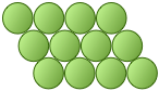
Directed chemical bonds between atoms have a major effect on the packing. The version of hexagonal packing shown at the right occurs in the form of carbon known as graphite which forms 2-dimensional sheets. Each carbon atom within a sheet is bonded to three other carbon atoms. The result is just the basic hexagonal structure with some atoms missing.
The coordination number of 3 reflects the sp2-hybridization of carbon in graphite, resulting in plane-trigonal bonding and thus the sheet structure. Adjacent sheets are bound by weak dispersion forces, allowing the sheets to slip over one another and giving rise to the lubricating and flaking properties of graphite.
Types of Holes From Close-Packing of Spheres
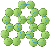
When a single layer of spheres is arranged into the shape of a hexagon, gaps are left uncovered. The hole formed between three spheres is called a trigonal hole because it resembles a triangle. In Figure \(\PageIndex{1}\), two out of the the six trigonal holes have been highlighted green.

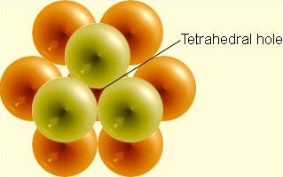
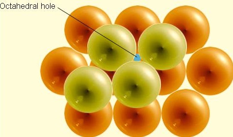
Once the first layer of spheres is laid down, a second layer may be placed on top of it. The second layer of spheres may be placed to cover the trigonal holes from the first layer. Holes now exist between the first layer (the orange spheres) and the second (the lime spheres), but this time the holes are different (Figure \(\PageIndex{2}\)). The triangular-shaped hole created over a orange sphere from the first layer is known as a tetrahedral hole because the surrounding spheres are in a tetrahedral arrangement. A hole from the second layer that also falls directly over a hole in the first layer is called an octahedral hole because the surrounding spheres are in an octahedral arrangement.
Close Packed Crystal Structures
Hexagonal Close-Packed (hcp)
In a hexagonal close-packed structure, the third layer has the same arrangement of spheres as the first layer and covers all the tetrahedral holes. Since the structure repeats itself after every two layers, the stacking for hcp may be described as "a-b-a-b-a-b." The atoms in a hexagonal close-packed structure efficiently occupy 74% of space while 26% is empty space.
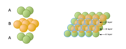 Figure \(\PageIndex{3}\): Side and top views of the layers in the hexagonal close-packed (hpc) structure.
Cubic Close-Packed (ccp)
The arrangement in a cubic closest packing also efficiently fills up 74% of space. Similar to hexagonal closest packing, the second layer of spheres is placed on to of half of the depressions of the first layer. The third layer is completely different than that first two layers and is stacked in the depressions of the second layer, thus covering all of the octahedral holes. The spheres in the third layer are not in line with those in layer A, and the structure does not repeat until a fourth layer is added. The fourth layer is the same as the first layer, so the arrangement of layers is "a-b-c-a-b-c."

Coordination Number and Number of Atoms Per Unit Cell
A unit cell is the smallest representation of an entire crystal. All crystal lattices are built of repeating unit cells. In a unit cell, an atom's coordination number is the number of atoms it is touching.
- The simple cubic has a sphere at each corner of a cube. Each sphere has a coordination number of 6 and there is 1 atom per unit cell.
- The body-centered cubic (bcc) has a sphere at each corner of a cube and one in the center. Each sphere has a coordination number 8 and there are 2 atoms per unit cell.
- The cubic closest packed, also called face-centered cubic (fcc) has has a sphere at each corner and each face of a cube. Each sphere has a coordination number of 12 and there are 4 atoms per unit cell.
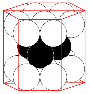
- The hexagonal closest packed has spheres arranged in hexagons with one in the center. each sphere has a coordination number of 12 and there are 6 atoms per unit cell.
Atoms Per Unit Cell
The amount that an atom contributes to a unit cell depends on its position in the unit cell
- Each corner atom contributes \(\frac{1}{8}\) to the unit cell in the cubic cells and \(\frac{1}{6}\) to the unit cell in hcp
- Each edge atom contributes \(\frac{1}{4}\) to the unit cell
- Each face atom contributes \(\frac{1}{2}\) to the unit cell
- Each center atom contributes 1 to the unit cell
| Unit Cell | Coordination Number | # of Atoms Per Unit Cell | % space |
|---|---|---|---|
|
Simple Cubic
|
6 |
1 | 52% |
|
Body-Centered Cubic
|
8 | 2 | 68% |
|
Face-centered Cubic
|
12 | 4 | 74.04% |
|
Hexagonal Closest Packed
|
12 | 6 | 74.04% |


Inorganic Crystals
Many common inorganic crystals have structures that are related to cubic close packed (face-centered cubic) or hexagonal close packed sphere packings. One component of the material will pack in one of the arrangements above. The remaining component(s) will fill some or all of the holes between the layers. An interstitial atom filling a tetrahedral hole is coordinated to four packing atoms, and an atom filling an octahedral hole is coordinated to six packing atoms. In both the hexagonal close packed and cubic close packed lattices, there is one octahedral hole and two tetrahedral holes per packing atom.
Are Anions or Cations Better Packing Atoms?
We might expect that anions, which are often larger than cations, would be better suited to the positions of packing atoms. While this is often true, there are many examples of structures in which cations are the packing atoms, and others in which the distinction is arbitrary. The NaCl structure is a good example of the latter.
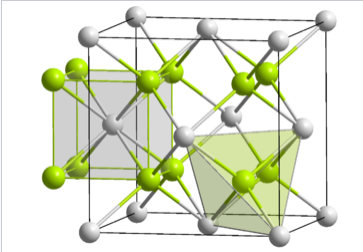
Rock Salt (NaCl)
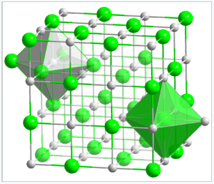
In the rock salt or NaCl structure, shown in Figure \(\PageIndex{5}\), the green spheres are the Cl- ions and the gray spheres are the Na+ ions. The packing atoms (Na+) are in a face centered cubic arrangement. The octahedral holes in a face-centered cubic lattice can be found at the edges and in the center of the unit cell, and they are filled by the chloride ions. Alternatively the structure can be described as the Cl- ions in a fcc arrangement with the Na+ ions occupying the octrahedral holes. Another way of stating this is that the structure consists of two interpenetrating fcc lattices, which are related to each other by a translation of half the unit cell along any of the three Cartesian axes. Thus the distinction between packing and interstitial atoms in this case is arbitrary.
NaCl is interesting in that it is a three-dimensional checkerboard, and thus there are no NaCl "molecules" that exist in the structure. When this structure was originally solved (in 1913 by using X-ray diffraction) by W. L. Bragg, his interpretation met resistance by chemists who thought that precise integer stoichiometries were a consequence of the valency of atoms in molecules. The German chemist Pfeiffer noted in 1915 that ‘the ordinary notion of valency didn’t seem to apply’, and fourteen years later, the influential chemist Armstrong still found Bragg’s proposed structure of sodium chloride ‘more than repugnant to the common sense, not chemical cricket’! Nevertheless, Bragg and his father, W. H. Bragg, persevered and used the then-new technique of X-ray diffraction to determine the structures of a number of other compounds, including diamond, zincblende, calcium fluoride, and other alkali halides. These experiments gave chemists their first real look at the atomic structure of solids, and laid the groundwork for X-ray diffraction experiments that later elucidated the structures of DNA, proteins, and many other compounds. For their work on X-ray diffraction the Braggs received the Nobel prize in Physics in 1915.
Since each type of atom in the NaCl structure forms a face-centered cubic lattice, there are four Na and four Cl atoms per NaCl unit cell. It is because of this ratio that NaCl has a 1:1 stoichiometry. The shaded green and gray octahedra in the NaCl lattice (Figure \(\PageIndex{5}\)) show that the Na+ ions are coordinated to six Cl- ions, and vice versa.
Other materials with the NaCl structure
- Alkali Halides (except CsCl, CsBr, and CsI)
- Transition Metal Monoxides (TiO, VO,..., NiO)
- Alkali Earth Oxides and Sulfides (MgO, CaO, BaS... except BeO and MgTe)
- Carbides and Nitrides (TiC, TiN, ZrC, NbC) -these are very stable refractory, interstitial alloys (metallic)
Other Unit Cell Types
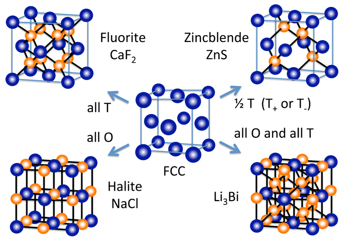
A number of other inorganic crystal structures are formed (at least conceptually) by filling octahedral and/or tetrahedral holes in close-packed lattices. Figure \(\PageIndex{7}\) shows some of the most common structures (fluorite, NaCl, and zincblende) as well as a rather rare one (Li3Bi) that derive from the fcc lattice. From the hcp lattice, we can make the NiAs and wurzite structures, which are the hexagonal relatives of NaCl and zincblende, respectively.
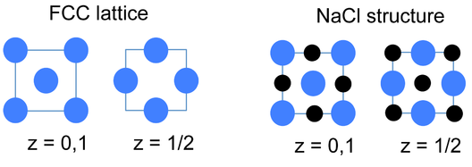
An alternative and very convenient way to represent inorganic crystal structures (especially complex structures such as Li3Bi) is to draw the unit cell in slices along one of the unit cell axes. This kind of representation is shown at the left for the fcc lattice and the NaCl structure. Since all atoms in these structures have z-coordinates of either 0 or 1/2, only those sections need to be drawn in order to describe the contents of the unit cell. It is a useful exercise to draw some of the fcc compound structures (above) in sections.
Fluorite
In ccp and hcp lattices, there are two tetrahedral holes per packing atom. A stoichiometry of either M2X or MX2 gives a structure that fills all tetrahedral sites, while an MX structure fills only half of the sites. An example of an MX2 structure is fluorite, CaF2, whose structure is shown in the figure at the left. The packing atom in fluorite is Ca2+ and the structure is composed of three interpenetrating fcc lattices. It should be noted that the Ca2+ ion (gray spheres) as a packing atom defies our "rule" that anions are larger than cations and therefore must be the packing atoms. The fluorite structure is common for ionic MX2 (MgF2, ZrO2, etc.) and M2X compounds (Li2O). In contrast, the hcp relative of the fluorite structure is quite rare because of unfavorable close contacts between like-charged ions.
In terms of geometry, Ca2+ is in cubic coordination with eight F- neighbors, and the fluoride ions are tetrahedrally coordinated by four Ca2+ ions. The 8:4 coordination geometry is consistent with the 1:2 Ca:F stoichiometry; in all crystal structures the ratio of the coordination numbers is the inverse of the stoichiometric ratio. Looking more closely at the tetrahedral sites in fluorite, we see that they fall into two distinct groups: T+ and T-. If a tetrahedron is oriented with a vertex pointing upwards along the stacking axis, the site is T+. Likewise, a tetrahedron with a vertex oriented downward is T-. The alternation of T+ and T- sites allows for efficient packing of ions in the structure.
Zincblende and wurtzite
Tetrahedrally bonded compounds with a 1:1 stoichiometry (MX compounds) have only half of the tetrahedral sites (either the T+ or T- sites) filled. In this case, both the M and the X atoms are tetrahedrally coordinated. The zincblende and wurtzite structures of ZnS are 1:1 tetrahedral structures based on fcc and hcp lattices, respectively. Both structures are favored by p-block compounds that follow the octet rule, and these compounds are usually semiconductors or insulators. The zincblende structure, Figure \(\PageIndex{10}\), can be thought of as two interpenetrating fcc lattices, one of anions and one of cations, offset from each other by a translation of 1/4 along the body diagonal of the unit cell. Examples of compounds with the zincblende structure include CuCl, CuI, ZnSe, HgS, BeS, CdTe, AlP, GaP, SnSb, CSi, and diamond. Using ZnS as a representative of zincblende, the coordination of both Zn and S atoms is tetrahedral.
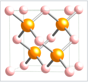 Figure \(\PageIndex{10}\): The zincblende structure of ZnS. The Zn2+ ions are in pink and the S2- ions are in orange.
The wurtzite structure is a close relative of zincblende, based on filling half the tetrahedral holes in the hcp lattice. Like zincblende, wurtzite contains planes of fused six-membered rings in the chair conformation. Unlike zincblende, however, the rings joining these planes contain non-planar, six-membered rings. The structure aligns the anions so that they are directly above the cations in the structure, a less favorable situation sterically but a more favorable one in terms of electrostatics. As a result, the wurtzite structure tends to favor more polar or ionic compounds (e.g., ZnO, NH4+F-) than the zincblende structure. As with zincblende, both ions are in tetrahedral (4:4) coordination and there are typically eight valence electrons in the MX compound. Examples of compounds with this structure include: BeO, ZnO, MnS, CdSe, MgTe, AlN, and NH4F.
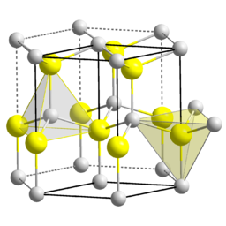 Figure \(\PageIndex{11}\): The wurtzite structure of ZnS with the tetrahedral coordination of anion and cation highlighted. The Zn2+ ions are in grey and the S2- ions are in yellow. (Public domain; Solid State via Wikimedia Commons)
An interesting consequence of the layer stacking in the wurtzite structure is that the crystals are polar. When cleaved along the c-axis (the stacking axis), crystals of ZnO, ZnS, and GaN have one negatively charged face and an opposite positively charged face. An applied electric field interacts with the crystal dipole, resulting in compression or elongation of the lattice along this direction. For this reason crystals of compounds in the wurtzite structure are typically piezoelectric (increasing the pressure on the material generates a voltage in the material).
Some compounds are diamorphic and can have either the zincblende or wurtzite structure. Examples of these compounds that have intermediate polarities include CdS and ZnS. SiO2 exists in polymorphs (crystobalite and tridymite) that resemble zincblende and wurtzite with O atoms midway between each of the Si atoms. The zincblende and wurtzite structures have efficient packing arrangements for tetrahedrally bonded networks and are commonly found in compounds that have tetrahedral bonding. Water, for example, has a tetrahedral hydrogen bonding network and is wurtzite-type. The undistorted wurtzite and zincblende structures are typically found for AX compounds with eight valence electrons, which follow the octet rule. AX compounds with nine or ten electrons such as GaSe and GaAs crystallize in distorted variants of the wurtzite structure. In GaSe, the extra electrons form lone pairs and this creates layers in the structure, as can be seen in the figure below. To the right of GaSe, the structures of As, Sb, and SbAs show an ever further breakdown of the structure into layers as more valence electrons are added.
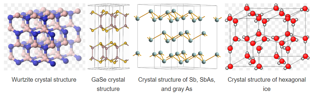
Hexagonal ice is the most stable polymorph of ice, which is obtained upon freezing at 1 atmosphere pressure. This polymorph (ice-I) has a hcp wurtzite-type structure. Looking at the structure shown at the right, we see that there are irregular arrangements of the O-H---O bonds. In the structure, hydrogen bonding enforces the tetrahedral coordination of each water molecule, resulting in a relatively open structure that is less dense than liquid water. For this reason, ice floats in water.
References
- Conway, J. H. and Sloane, N. J. A. Sphere Packings, Lattices, and Groups, 2nd ed. New York: Springer-Verlag, 1993.
- Krishna, P. and Verma, A. R. Closed Packed Structures, Chester, UK: International Union of Crystallography, 1981.
- Petrucci, Ralph H., William S. Harwood, F. Geoffrey Herring, and Jeffry D. Madura. "Crystal Structures" General Chemistry: Principles & Modern Applications, ninth Edition. New Jersey: Pearson Education, Inc., 2007. 501-508.
Contributors and Attributions
Stephen Lower, Professor Emeritus (Simon Fraser U.) Chem1 Virtual Textbook
- Brittanie Harbick, Laura Suh, Jenny Fong