
The gas system
- Page ID
- 61153
Nico Vonk, Avans+, Breda, The Netherlands
Abstract
The problems encountered in the gas system, the components of the carrier gas system, tubing, connectors, and detectors are listed and discussed in detail.
Level: Basic
The design of the entire gas system is similar for all GC apparatus. The parts of the system are either directly connected or by means of a length of tubing between the components.
More details on the gas system can be found in the chapter on the gas system.
The common problems encountered in the gas system are listed below. Gas problems in the injector, in the detector or in the column will be dealt with in other chapters.
| Part and Problems of the Gas Systems | |
| Part of the Gas System | Problems of the Gas System |
| Gas cylinder or gas generator | Gas supply: amount and storage |
| Gas mains, compounds and connections | Leaks |
| Pressure regulator, flow control | Contamination |
| Pressure gauge | Pressure control |
| Filters | Contamination |
| Injector | Leaks |
| Column | |
| Detector | Wrong flow settings |
Detector gas systems are, with the exception of the injector and the column, comparable to carrier gas systems. There is a direct connection between flow controller/pressure regulator and the detector.
Viscosity
Commonly used gases in GC are nitrogen, helium, hydrogen (compressed or synthetic) air and argon/methane. A number of factors play a role in choosing a carrier gas, one of which is viscosity. Gases have, just as liquids, a certain "flow thickness", viscosity.
H-u Curves and Efficiency of Three Gases
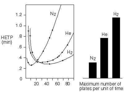
This illustration shows that:
- Heavy carrier gases give the highest efficiency in the optimum. However, this optimum lies in the low gas velocity area leading to a long analysis time.
- Increasing the temperature will lead to loss in plate number.
- Helium and hydrogen give less loss with higher velocities.
- For maximum column efficiency use nitrogen. For short analysis time use hydrogen or helium, this may improve analysis time with a factor of three.
Viscosity is determined by:
- The density. The number of molecules per unit volume which according to the gas laws of Boyle and Gay-Lussac is dependent on the pressure and the temperature.
- The type of molecules (molecular weight, geometric form, interaction forces).
The higher the viscosity, the larger the pressure per column length-unit. The viscosity of the carrier gas is important to obtain a certain flow with the required pressure. One should pay attention to that especially if one works with long columns.
The viscosity of gases is temperature dependent. Contrary to liquids, the "flow thickness" increases when the temperature rises. So there is no problem with isothermal analyses, but if increasing column temperatures are used (temperature programming):
- The flow will become smaller with a fixed set pressure
- The pressure will become higher with a fixed set flow.
A temperature increase of 250ºC means in a constant pressure regulated system a reduction of about 50% of the gas flow through the column!
At temperature programming the viscosity effects can be clearly noticeable. Flow regulated systems will not produce a change in conditions, but the pressure drop over the column changes with temperature during the analysis.
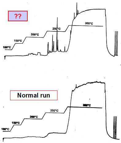
Blank column background temperature program
With increasing temperature the stationaire phase and residues from previous samples will evaporate and elute from the column. This is called 'bleeding' and will show as a raising baseline in the chromatogram. With good and clean columns the bleeding should not be visible below 200°C.
Blank Column Background Temperature Program: What's this?
Purity & Filtering
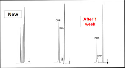
Gases should have a high enough purity in order to be used as carrier gases. Reactive components, including water and oxygen, can seriously damage the stationary phase:
- Oxygen can lead to oxidation resulting in a change in retention values, loss of resolution and peak tailing.
- Water can damage, as a result of hydrolysis, both the stationary phase, the sample components and the support material.
- Not only the actual support material as in packed columns could be destroyed but also the deactivated fused silica of the capillary columns. Hydrolysis becomes evident in baseline noise and increased peak tailing.
Oxygen can Damage Your Column
| Table: Purity of Gases | ||||
|
Gas |
|
Purity |
Maximum Water content |
Maximum Oxygen content |
|
Helium |
4.6 |
99.996 |
5 |
5 |
|
|
5.0 |
99.999 |
1 |
3 |
|
|
5.6 |
99.9996 |
0.7 |
2 |
|
Hydrogen |
4.3 |
99.993 |
2 |
20 |
|
|
5.0 |
99.999 |
1 |
5 |
|
|
5.6 |
99.9996 |
1 |
2 |
|
Nitrogen |
4.6 |
99.996 |
5 |
5 |
|
|
5.0 |
99.999 |
2 |
3 |
|
|
5.6 |
99.9996 |
0.5 |
1 |
|
Argon |
4.8 |
99.998 |
3 |
4 |
|
|
5.0 |
99.999 |
2 |
3 |
|
|
5.6 |
99.9996 |
0.7 |
1 |
Not only carrier gases must be sufficiently pure, but also gases necessary for detector operation should be clean as well.
In highly efficient capillary columns with a very low amount of stationary phase, contamination in the carrier gas will immediately result in visible damage. That is why a high purity level is required, minimum 5.0.
If one also expects a high sensitivity, it makes an extra demand as to the purity: impurities cause noise. This only increases exponentially at higher oven temperatures. When using filters in the gas mains and the correct purity, one prevents all kinds of problems that may result from impurities.
Mind that not so much the purity of the gas when it comes from the gas cylinder or from the filter is important, but the purity when it enters the gas chromatograph. Small leaks in the gas mains, incorrect handling, insufficient flushing of the gas mains after exchanging the gas cylinders, can ruin all precautions.
The same also applies to when pressure gauges or gas regulators are used of inferior or lesser quality, e.g. pressure regulators with synthetic membranes rather than stainless steel. Fortunately, leaks can be detected quite quickly nowadays by alarm systems, notably in the small compartment of the GC-oven.
| in Practice the Following Filters are Used | |
| For carrier gases: |
Inlet -> Moisture filter -> Oxygen filter -> Injector. |
| For FID-fuel gases: | An active charcoal filter to remove organic compounds. (Inlet -> Charcoal -> Detector) |
| For ECD- make up gas: |
A moisture filter to remove water and sometimes traces of oil from connections or pressure gauges. |
Safety
Hydrogen is extremely flammable. Mixtures of of hydrogen and air (oxygen) are explosive. Safety should be the first consideration. Even though capillary GC has only small gas flows, unsafe situations can result in serious problems. As long as hydrogen is in a closed gas system nothing can go wrong. However, a GC gas system is never a completely closed system:
- The gas can flow freely at the split outlet. This does not cause any problem since the gas stream from the column is instantaneously burned up in the flame ionization detector.
- If it could get out earlier (e.g. if there are leakages) the situation can be very unsafe. This risk exists in particular when a capillary column is broken near the injector.
Gas Supply with Cylinders
Most gases come in cylinders, compressed up to 200 bar. Each cylinder has the name of the gas stamped on it and the cylinder has been painted in a particular colour to identify the gases contained in it:
| The Color of Gas Bottles | |
| Helium | Brown |
| Argon | Dark green |
| Hydrogen | Red, left-handed screw |
| Nitrogen | Bright green |
| Air | Blue |
| Argon/Methane | Dark green with ochre band |
- Cylinders should be well secured and placed in a ventilated, dry and fireproof room.
- Cylinders can be opened or closed with a valve. This valve should only be used if the gas cylinder is connected to the system. Bear in mind that pressures up to 200 bars without resistance can produce very high gas flows.
- If rust particles are present, blow them away carefully before connecting.
- Always use suitable tools when connecting or disconnecting and make sure that the reducing valve has been closed enabling as little air as possible flowing into the gas line system.
- When changing the gas cylinders it is important to replace the 0-ring or seal which is forgotten quite often. It is essential to flush the first part up to the first valve/reducing valve of the gas lines because there is always some air present when the cylinders are changed. If this is not done the filter (and notably the oxygen filter) would get overloaded.
- We advise to mark the tubing system in the vicinity of the cylinders and also near the gas chromatograph, for instance with pieces of tape in the same colour as the cylinder.
Pressure Gauges
Pressure gauges are incorporated in the system to check and reproduce the gas pressure. They reproduce the gas pressure in the atmosphere (technical or physical) bar, psi or Pascal. They provide the first sign if something is wrong with the gas supply. Make sure that there are enough pressure gauges within the system:
- One on the cylinder or generator for the pressure supplied.
- One in or close to the gas chromatograph for the inlet pressure received from the gas supply network.
The following definition and conversion factors can be used:
1 Pascal = a pressure of 1 Newton per m2 (N/m2)
1 physical atmosphere (atm) = a pressure of a 76.000 cm mercury column at 0ºC
1 technical atmosphere (at)= a pressure of 1 kg weight per cm2
1 bar = 1.0 x 105 = 100 kPa = 0.1 Mpa
1 psi = 1 pound per square inch
Although Pascal (kPa and MPa) is the official unit (in Europe) according to the SI unit system, units like bar and atmosphere are used indiscriminately in practice. The psi is very popular in English speaking countries.
| Units of Pressure | |||||
| 1 kPa | 1 atm | 1 at | 1 bar | 1 psi | |
| 1 kPa | 1 | .000967 | .00192 | .0018 | .00145 |
| 1 atm | 101.3 | 1 | 1.03 | 1.013 | 14.7 |
| 1 at | 98 | .97 | 1 | .98 | 14.3 |
| 1 bar | 100 | .987 | 1.02 | 1 | 14.5 |
| 1 psi | 6.9 | .0680 | .070 | .0689 | 1 |
Flow Measurement
An external flowmeter is an instrument which should be part of the standard equipment of the gas chromatographic laboratory. They are not only used to set an adequate flow when the apparatus is switched on but also to measure the actual gasflow at various places when problems are encountered in the gas supply.
The four most widely used flowmeters are:
- The differential manometer. A differential manometer measures the pressure drop occurring just after a constriction in the tube. This pressure drop is the result of the increased rate with which the gas flows through the constriction. The pressure drop can be calibrated on the flow rate and thus the amount of gas. As the calibration depends on the type of gas being used, there are devices available with various scales for various gases as well as devices with 1 scale but with different calibrations. These flowmeters are accurate and easy to use.
- The analogue or digital flowmeters.The analogue or digital flowmeters based on the measurement of an internal resistance or a thermal transfer in a measuring cell as a function of the flow and the type of gas. They are easy to use but have to be calibrated from time to time.
- Soapfilm meter. The simplest and most inexpensive flowmeter is the soap film meter. The rate of a moving soap film is measured in a volumetric calibrated tube by means of a stopwatch. Such simple gas flow meters have a surprisingly good accuracy. Only at low flows and then especially with hydrogen and helium the accuracy is not too good. Hydrogen and helium can diffuse through the soap film which leads to loss of flow. A simple way to intercept this is creating a pre-chamber: the gas flow is measured by means of a second soap film. The space between the first and the second soap film, filled with the same gas, should be a sort of intermediary.
When an accurate determination of the capillary column flow is desired, calculate this by means of the dead time (t0). The column flow is equal to the column volume Vc divided by the dead time:
\[F=V_c / t_0 =\dfrac{1}{4} (p d_c^2 L) / t_0\]
The dead time is the time as from the moment of injection of an unretained component until the elution. In the following table components are mentioned which can be used in certain detectors as unretained components.
| Components to Determine the Dead Time to of the Column | |
| FID | Methane, (propane or butane at higher column temperatures) |
| TCD | Air, Methane |
| ECD | Methylene chloride-vapour (mono chloro methane) vapour to be obtained by head space |
| NPD | Acetonitrile-vapour |
| MS | Air, methane, argon |
Tubing
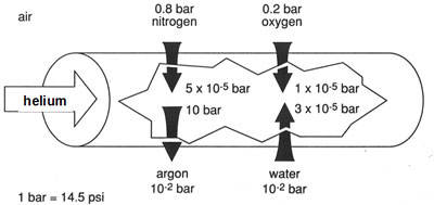
The best materials for the tube system are copper and stainless steel. Not on account of their pressure resistance, but due to their non-permeability of gases. Totally gas tight thermoplastic synthetic materials, like teflon, do not exist. This type of material has openings of 0.01 µm are for gases, such as helium, already permeable.
When using, for example, Teflon as tubing material, or as diaphragm in reducing valves two kind of problems may occur:
- Carrier gas, but also detector gases, can diffuse through the tubing wall.
- Oxygen can enter due to diffusion. If oxygen or organic contaminants come into contact this influences the stationary phase and effects the retention times, the peak shape and the detector signal (incl. the baseline).
Metal tubing do not have these problems. Yet copper and stainless steel tubes can also be a source of problems which is usually the result of contaminated tubing walls. In particular traces of oil and grease from the production process can, for quite some time, contribute to noise, an unstable baseline or a reduced sensitivity. Impurities in tubing after the injector can also give physical and chemical reactions with the sample components.
We strongly advise you to let gas mains installed by a specialised firm or by your own experts.
Leak Detectors
The most common problems in the gas system are the result of leakage, which can be located by means of leak detectors.
- Thermal Conductivity leak detector: a "dry" electrical instrument which measures the difference in thermal conductivity at the place of the gas leak in respect of the air of 1 atmosphere. These detectors are very sensitive and particularly suitable to locate small leaks.
- "Snoop":a liquid soap solution which detects a leak through gas bubbles. This can be used up to 100 ºC and will boil above this temperature. Don't use Snoop inside the GC oven!
- Portable mass spectrometer with a mass range of 1 to 20 amu (very expensive).
The electrical leak detector is the most suitable instrument.
Leaks
Leaks in a GC gas system practically always occur at connections caused by:
- Improper handling of connections and fittings
- A wrong combination of couplings of a different brands which are not (completely) interchangeable.
All fittings are of the compression type: gas cylinder connections with a flat or convex compression type fitting (seal), column connections with a conical fitting (ferrules).
Some particular brands of cylinders do not have a seal anymore due to a leak tight metal-to-metal construction.
The connection of the tubing system to the gas chromatograph is usually done by means of a 1/16" or 1/8" female nut (depending on the line thickness) with a ferrule. Always make sure of the make of the gas chromatograph-connection and use the appropriate type of nut and ferrule.
The thread, the angle of the conic the ferrule has to seal, the shape and length of the ferrule and the insert length of the fittings vary so widely from one manufacturer to another that interchanging might cause serious difficulties.
If, however, you do try to connect it will at least result in leakages or in damaging the thread of the connection and maybe that part of the apparatus.
Connecting Columns
The connection of a metal packed column is done the same way as described before. As to the measurements of ferrules is valid that those for packed columns are generally given in inches. For example: a ferrule with the measurements 1/8" x 1/16" has an outside diameter of 1/8" and such an internal diameter that it is suitable for columns and tubing with an outside diameter of 1/16".
In soft ferrules such as graphite the "tight is tight" is applicable. Hand tight is usually sufficient. These ferrules must be used for glass packed columns or fused-silica capillary columns.
When using too much force the ferrule can be distorted and leakage is the result.
Metal capillary columns are coupled the same way as fused silica columns. When using capillary fused silica columns one can choose from 3 types of ferrules:
| Types of Ferrules | |||
| Material | Maximum Temperature | Bleeding | Possibility to Use Again |
| Graphite | 400ºC | none | good |
| Vespel | 350ºC | little | good |
| Teflon | 225ºC | substantial | poor |
Special attention should be paid to the size of the hole in the ferrule. Make sure that it corresponds to the outside diameter of the column. It will prevent deformation of the ferrule and thus a better sealing. If there is no proper sealing the capillary column might break.
| Ferrule Size for Capillary Columns | ||
| Column Inner-Diameter | Column Outer-Diameter | Ferrule Inner-Diameter |
| 0.15 mm | 0.35 mm | 0.40 mm |
| 0.25 mm | 0.35 mm | 0.40 mm |
| 0.32 mm | 0.45 mm | 0.50 mm |
| 0.53 mm | 0.70 mm | 0.80 mm |