
Dual Slope ADC
- Page ID
- 60154

For the ADCs discussed to this point, a time-varying signal was sampled or the ADC operated so rapidly that, for practical purposes, the signal did not change during a single conversion. Now we go to the other time extreme. What if there is a noisy signal, and we desire to digitize its average value? For example, what if we're looking at a flickering candle and we want to know the average illumination? One strategy would be to digitize at a high rate (say, with a successive approximations ADC) and average the results. But another strategy is to do signal averaging in the midst of the digitization process, thus simplifying the electronics. The dual slope ADC is one of several devices that work in this way.
How long does it take to go down a flight of stairs? "It depends how many steps there are," you obviously reply. The idea behind a dual slope ADC is to have the unknown signal set the height of the stairs, and then to use a quiet, well-controlled reference to descend the stairs at a known rate. If we know the rate, and we measure the time, we know how high the stairs are. Now let's translate that into electronics.
Aside from comparators, the most important analog part of a dual slope ADC is an integrator. The circuit is:
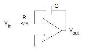
Vout is the integral of Vin, or actually
\[V_{out} = - \dfrac{1}{RC} \int _ o^T V_{in}(t) dt\]
Any time one wants to reset the integral to 0, one simply shorts the capacitor. Notice the negative sign -- positive input voltages give negative output voltages.
If we want to digitize a postive voltage, we'll also need a reference voltage that's negative (and, of course, if we want to digitize negative voltages, we need a positive reference). We integrate the unknown voltage Vin(t) for a fixed time T. For now, let's assume the potential is constant in time. The integral will be -VinT/RC. Now disconnect the input potential. Since the input is 0, the integral holds constant. Next, connect the input to the reference voltage (opposite sign to Vin) and integrate. What will happen? The integrator will ramp towards 0. How will we know when we get to zero? Multiple choice, choose the right component:
How long will it take for the integrator to reach zero? Long enough to exactly give the same magnitude but opposite sign integral we just computed above. Leaving out the signs, VinT/RC = VrefTdown/RC. How convenient -- the RC values cancel. Tdown=VinT/Vref. Since T and Vref are fixed, the time that the down count takes is proportional to the input voltage. If we're clever (and why wouldn't we be?), we can get the down-count time to read out as if the units were volts. If the magnitude of Vref is 5 V, and the input voltage that we're trying to measure is 1.000 V, then we want something that will count to 1000 time units. Suppose we have a clock that puts out one pulse every 10 μs. Then if Tdown is 1000 × 10 μs, we have it. But that makes Tdown=10 ms, so T (the integration time) must be set to 10 ms * 5.000 V/1.000 V = 50 ms. But once we set the initial integration time to 50 ms, the time that it takes to return to 0 will read out in voltage directly. For example, if we integrate 2.345 V for that same 50 ms, then the discharge back to zero will take 2345 ticks of the 10 μs clock, and we have the readout as we wanted it. Here's a sketch of what we just said:
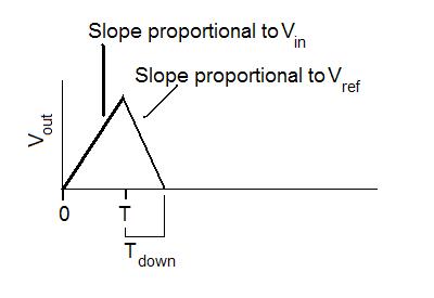
So why do it this way? Suppose that there is noise on top of the input voltage. By integrating, we average out the noise, thus getting a precise measurement of the input potential. Additionally, measuring time precisely is easier than measuring potential precisely. We can get additional bits in our measurement by using a faster clock (and thus a higher count for the same discharge time) much more easily than by adding bits to a flash or successive approximation converter. For the same mean as in the sketch above, a noisy signal would be digitized thus:
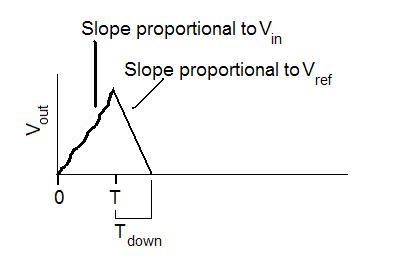
The zig-zag increase in potential is due to noise on the input signal, but that averages out over time T.
Remember that there are multiple ways to format binary numbers? Which of the common forms would be easiest to use with a dual slope ADC?
Let's put the pieces together. What would a complete dual slope ADC look like inside? We'll leave out the details of the counter/controller. Dashed lines mean "control" (to throw a switch or convey a pulse). Solid lines carry analog potentials. The circuit is:
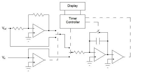
The system works in 3 stages:
1) short the capacitor to set the integrator to 0.
2) integrate Vin for fixed time.
3) use either Vref or - Vref to drive the integrator back to zero, with the timer measuring the elapsed period until a "stop" pulse is received from the comparator observing the output of the integrator. The time than transfer Tdown to the display, where it is shown until the completion of the next 3 step cycle.
In the days when analog integrated circuits were cheaper and more familiar to designers than digital circuits, the dual slope ADC was the choice for inexpensive multimeters, anything that didn't require high speed, and especially any problem that looked at noisy signals. Now that microcontrollers with high speed ADCs and facile signal averaging are available, the dual slope system is becoming less common. Nevertheless, when considering measurement of noisy signals, as long as conversion rates of no more than 10 times per second are adequate, this is an approach that is well worth considering. The sigma delta ADC, linked with a digital signal processor or microcontroller, is becoming the chief challenger to the dual slope system.