
Experimental Section
- Page ID
- 60471

Instrumental setup.
The microchip CE and LIF detection setup has been described previously in the literature.17 A listing of the components that are needed to assemble the microchip CE and LIF detection setup are included as part of the electronic materials accompanying this document. A schematic diagram of the instrumentation is shown in Figure 1, and a photograph of the setup is given in Figure 2. In this setup a solid-state laser is directed through a 10X beam expander into the optical input of a fluorescence microscope. The excitation source goes through a 488 nm excitation filter and reflects off of a dichroic filter before being focused via a 20X 0.45 NA microscope objective into the separation channel. Fluorescent light is collected via the same objective, and then passes through the dichroic and longpass filters before being spatially filtered via a confocal pinhole prior to photomultiplier tube (PMT) detection. The PMT signal is converted to voltage, filtered with a pre-amplifier and digitized with an analog-to-digital converter (ADC) to enable collection as detector signal vs. time using a designed LabView virtual instrument. This LabView program is included as part of the electronic materials accompanying this document. For researchers lacking access to lasers, a UV source coupled with a filter cube can also be used for fluorescence detection.
Microchip CE is carried out using a “pinched” injection scheme,17, 18 wherein sample is placed into reservoir 1 (see Figure 1), and buffer solution is in the other three reservoirs. Applying a positive potential to reservoir 3 while grounding the other three reservoirs for a time interval causes sample loading into the injection intersection. Electrophoretic separation is then carried out with reservoir 2 grounded, reservoirs 1 and 3 at an intermediate positive potential, and a higher voltage applied to reservoir 4. Voltages are switched using relays built by the BYU Chemistry and Biochemistry Department Instrument Shop. Because the microchip is on a microscope stage, the focused laser can be positioned anywhere within the channels, but for optimal performance, the laser is usually aimed near reservoir 4 in the separation channel.
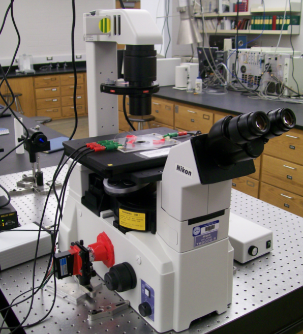
Figure 1. Schematic diagram of the microchip CE and LIF detection setup
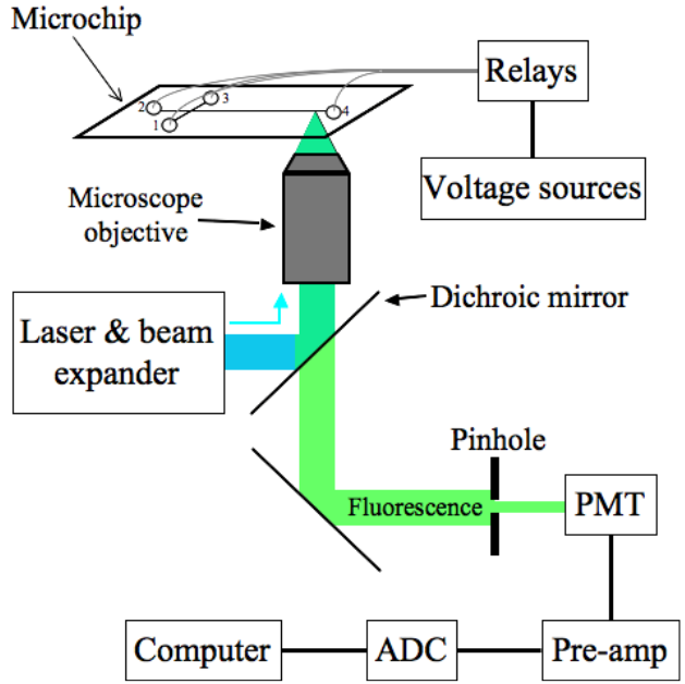
Figure 2. Photograph of the microchip CE and LIF detection instrument.
Microchip fabrication.
Microchip CE devices are fabricated using a hot embossing and thermal bonding approach that has been described in the literature.14, 16, 17 The channel design is transferred (via photolithography) to a silicon wafer; the pattern is wet etched into the silicon using 40% potassium hydroxide, to provide hot embossing templates. Hot embossing of the poly(methyl methacrylate) (PMMA) devices occurs at 140 ºC under C-clamp pressure, and thermal bonding of the embossed channels to a blank PMMA substrate with laser cut reservoir openings is done at 110 ºC in a manner similar to the hot embossing.
We had an experienced graduate student carry out device fabrication for the experiment. However, we note that it is feasible for a graduate student teaching assistant or even an undergraduate student (see the Results and Discussion) to be trained in a short time to reliably carry out the thermal bonding of devices from the hot embossed and drilled PMMA pieces. Moreover, we are willing to provide (at cost) hot-embossed PMMA microchannel substrates and laser-cut cover plates to educational institutions that are interested in developing this microchip CE experiment. We further note that PMMA microchip CE devices are available commercially (e.g., from Microfluidic ChipShop, Jena, Germany) at a cost of ~$10/device if purchased in bulk.
Sample preparation.
The amino acids are labeled fluorescently using fluorescein-5-isothiocyanate (FITC; Molecular Probes, Eugene, OR), as we have reported in a prior publication.13 We combined 200 μL of 6 mM FITC in dimethyl sulfoxide with 600 μL of a 3 mM solution of the amino acids. The solutions are left to react at room temperature in the dark for >24 h (even longer times led to more complete reaction and elimination of the unconjugated FITC peak).
Laboratory write-up.
The experimental instructions that are given to the students are included as part of the electronic materials accompanying this document.