
4.2: Flow Injection Analysis (FIA)
- Page ID
- 76117
Batch techniques for measuring the intensity of chemiluminescence are sometimes used, some of which incorporate automation to improve sample throughput [1], but flow methods are applied much more often. A suitable flow injection manifold[2] is shown in figure D2.1.
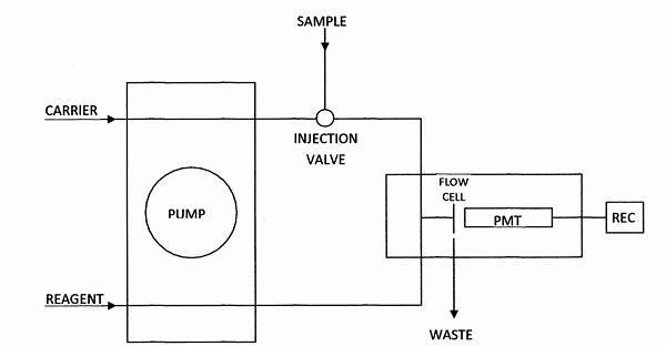
A flow injection manifold for measuring chemiluminescence (PMT = photomultiplier tube; REC = recorder).
Flow injection manifolds are constructed from polytetrafluoroethylene (PTFE) tubing to contain the sample while it is chemically or physically modified prior to detection. Liquid is usually transported from reservoirs by means of a peristaltic pump with suitable tubing. An accurately measured volume of sample is reproducibly introduced into a carrier stream by means of a rotary injection valve. The detector is connected to some means of data-storage. The signal depends on the rate of the reaction producing it and on flow-rate, tubing dimensions, reagent addition order and flow-cell volume, which should be large enough to ensure that a high proportion of the total emission enters the detector; optimisation will favor conditions that lead to emission occurring during the passage of the sample through the flow-cell. The flow-cell should be so positioned as to make this possible, e.g., directly in front of the window of a photomultiplier tube and in a box that excludes ambient light. FIA has important advantages over batch methods. It makes use of simple and relatively inexpensive apparatus, which is readily miniaturised and has great potential for adaptation and modification. Easy operation and high sampling rates are possible.