
4: The Alane-Amine Adduct (C₂H₅)(CH₃)₂N:AlH₃ (Experiment)
- Page ID
- 127286
This experiment is adapted from the textbook (pages 47-53).
Safety Notes:
- Both lithium aluminum hydride (“LAH,” formula LiAlH4) and the alane-amine complex are highly moisture sensitive and react violently with water.
- Throughout this experiment, be extremely mindful of the direction of air flow and monitor the bubblers to ensure that the pressure remains positive but modest. A rapid flow through the bubbler may result in the loss of the oil and the potential for a loss of integrity in the system.
- Whenever positive pressure is placed upon a flask or is likely to result from a reaction (any gas evolution), a vent must be present in the form of a needle or cannula except in the case of momentary transitions.
- In no scenario should vacuum be applied to a flask that still has a vent to the atmosphere. This may result in loss of product, fire, or explosion.
- Every flask must be secured by a clamp at all times that it is in use. The flasks being used are pear-shaped Schlenk flasks, most stable and durable for vacuum, but largely impossible to safely secure in the appropriate orientation without a clamp.
- For the second day of the experiment, students must wear a Bulwark FR laboratory coat (obtained from the dispensary for the day) and flame-resistant gloves.
Day 1 - Practice using a Schlenk manifold system.
The compounds used in this experiment are not necessarily more sensitive than those in the other air-free experiments; however, their interaction with the atmosphere is potentially more violent and noticeably more dangerous. To address this increased risk, this short experiment is prefaced with direct experimental technique practice.
Glassware maintenance
Schlenk flasks are stored in the oven at ~120° C to drive off any moisture that may cling to the surface or within the pores of the glass, itself. At the beginning of class, the flasks and stopcocks should be in the oven. Remove them with heat-resistant gloves and set them on a non-plastic surface to cool. Once they are still warm but safe to touch (this should take only 2-3 minutes), the stopcock must be lubricated with vacuum grease and placed in the valve, then secured with a metal clip. Rotate the stopcock repeatedly to ensure the most complete coverage of grease, then wipe any excess from the surface of the glassware. Note that excessive grease will work its way into the channel and may contaminate either the hose or the interior of the flask.
When a flask is no longer needed, it needs to be dissembled and cleaned thoroughly. Use paper towels to remove the majority of the vacuum grease from the valve joint and stopcock, then wash everything with soap and water. Rinse with tap water, then deionized water. At this point, be prepared to wash a second time or rinse with acetone, depending on the nature of any suspected persistent materials still clinging to the flask. The final rinse should be deionized water, then the glass pieces must be placed back in the oven to dry for the next lab.
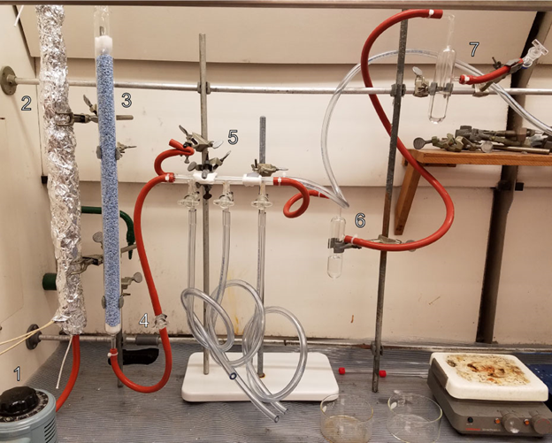
Figure 1 - Alane Schlenk Diagram. 1) Rheostat for heating element 2) oxygen scraper 3) drying column 4) valve to isolate columns 5) three-valve Schlenk manifold 6) first bubbler 7) second bubbler and final N2 valve. Clear hose on the right connects to solvent trap for vacuum line.
Purging the atmosphere of a flask
Any fresh flask connected to a Schlenk line via hose has likely been exposed to atmosphere to some degree. Before an empty flask can have any sensitive materials transferred into it, the interior must be purged. The flask should have a fresh septum covering any openings, rolled down over the edge and secured with a zip-tie or rubber band about the septum lip. Any time a flask is going to be placed under positive pressure from any source, the septa must be secured in this fashion. The pressure required to cause a septum to pop out of a machined glass neck is surprisingly small. Connect the hose to the stem and turn the manifold’s valve to vacuum. At this point, open the valve on the flask’s stem. The sound of the pump will change as the pressure spikes and is drawn down. The perturbation of the idle noise is a good indicator of the status of the pressure. Once most of the atmosphere has been removed, slowly turn the manifold valve to the nitrogen line to re-fill it - this only takes a few seconds. Pull vacuum again and refill with nitrogen three times total. Once complete, it is generally best to close the valves until the follow-up operation is ready.
Each time the purge-fill cycle is performed, the original atmosphere is removed in percentages. It can never be perfect, but if the pressure in the flask drops from 760 torr to 76 millitorr (not unreasonable with a moderate strength pump), then the oxygen in the flask has been reduced by four orders of magnitude, or 0.01% of its original. Two more identical cycles should reduce the oxygen to negligible levels.
Removing solvents with a syringe
Solvents isolated from atmosphere have a few challenges to address. First, their containers are sealed, so solvent removal must come with a similar volume displacement. Second, the syringe itself can be a source of contamination. Needles used for this purpose tend to be long and quite bent.
Before placing a syringe into a sealed solvent container, the needle end should be placed into a hose connected to the manifold with a positive nitrogen flow. At this point, the plunger should be drawn in and pushed downward 3-5 times. Finally, pull the plunger back to fill it with nitrogen, then place the needle on the septum and pierce it. Once punctured, press the plunger to add the nitrogen in the syringe to the head space (air above a solvent) of the container. At this point, place the point of the needle into the solvent and bend needle so that the syringe faces upwards, then draw the plunger back until the desired quantity is obtained. Pull the tip of the needle out of the solvent and draw in around 1-2 mL of vapor from the bottle to shield the solvent from atmosphere for transport and draw the solvent fully into the syringe. At this point, the needle is ready to be withdrawn and placed through the receiving vessel’s septum for dispensing. When drawing solvent up, the syringe should point upwards and when dispensing it should point downward.
Transferring solvents with a cannula
Transferring liquids from one sealed vessel to another requires the use of a cannula, or a two-ended needle. Like Schlenk flasks, it should be stored in the oven to keep it dry between periods, but is always purged of air inside it before any transfer is performed.
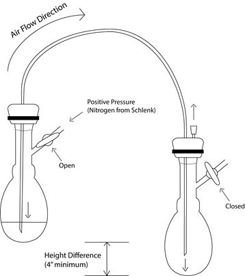
Figure 2 - Basic Cannulation diagram for transfer. Note that both flasks must be secured with clamps.
First, both flasks should be already sealed with septa secured with zip-ties. Only the flask serving as the source is connected to the Schlenk manifold by hose. Positive nitrogen pressure is placed on the source flask, the pierce the source flask’s septum with first end of the cannula. Once the cannula is inserted, the other end acts as a vent for the pressure in the first flask, preventing backflow of atmosphere. The cannula remains above the solvent in the head space at this point, so that only gasses are passing through it. Next, pierce the second flask with the other end of the cannula. Now the nitrogen flow is entering the first flask, going through the cannula, and entering the second flask. At this point, pierce the septum of the receiving flask a second time with a small needle to allow the pressure to vent. Observe the bubbler and note whether the speed of the bubbling has decreased now that there is a second path for the nitrogen gas. Once this step is reached, the first end of the cannula can be placed into the liquid to be transferred. The transfer itself may happen slowly or rapidly, depending on the needs of the reaction. If no liquid has transferred after ~30seconds, then the pressure may need to be increased by closing off the vent at the end of the bubbler system. If the pressure in the system is too high, this may put strain on the system and risk popping a septum that has been insufficiently secured, ruining the efforts to keep the solvent or solution isolated. If the bubbler valve was closed for this transfer, be certain to open it immediately upon the transfer’s completion, but to do so very slowly. With rapid pressure changes, the oil in the bubbler may be either ejected or drawn into the manifold itself, and both of these negatively impact the integrity of its ability to maintain an inert atmosphere. This is also the reason why vacuum is not used on the receiving flask to accelerate the transfer – it is certain to overpower the nitrogen pressure and draw in atmosphere through the bubbler system after sucking the oil into the manifold.
After the transfer is complete, the steps are undone in the reverse order. The vent needle is removed, first. The cannula is withdrawn from the receiving flask. The cannula is withdrawn from the original flask. Then the nitrogen pressure is disconnected from the flask. At this point, the cannula itself should be mostly dry on the inside, but should not be re-used without careful consideration regarding contamination. A clean solvent transfer followed by a solution of that solvent is a non-issue, but a solution cannot be followed by a clean solvent while retaining the expectation of cleanliness.
When done using a cannula, rinse it with deionized water, flush it out with air pressure, and replace it in the oven to keep it dry. When not in use, cannula are generally stored in a twisted loop. Your TA can demonstrate this.
Reducing solvent volume under vacuum (solvent trap use)
One of the most common uses for the vacuum access on a Schlenk manifold is to use the reduced pressure to help a volatile solvent evaporate. This is significantly simpler than the other operations. However, it must be ensured that the solvent trap is prepared. The trap is a large two-piece glassware assembly that looks like one of the bubblers on a larger scale. The two pieces are joined at a ground-glass joint that must be lubricated with vacuum grease to maintain a seal while preventing the joints from fusing. These two pieces may be separate when you arrive, requiring greasing and assembly. A dewar of appropriate size for the trap should be half-filled with liquid nitrogen, and secured about the trap itself with cotton insulation wrapped around the top to minimize temperature loss. This functions to condense any gasses drawn into the manifold by the vacuum system and prevent them from entering the pump itself. Gasses that pass through the trap successfully end up in the oil of the vacuum pump and then being exposed to the heat that the pump’s operation creates – this is a danger if the gas is flammable, as most organic solvents are. In addition, the gasses that enter the oil are also expelled from the pump by evaporation, resulting in the rapid spread of any smells they may have and the potential dissemination of inhalation-based health risks. If the trap is exposed to atmosphere, liquid nitrogen is capable of condensing gaseous oxygen into liquid oxygen, a dangerous and explosive liquid. It is for this reason that the manifold must never be exposed to atmosphere while the trap is up (connected and sealed) and cooled, and vacuum must never be drawn on a solvent without the trap being up.
A flask sealed with a secured septum is connected to the manifold by one of the hoses. The manifold is turned to vacuum and the valve on the flask is opened. The solvent may begin to boil, but the volume of the flask should be selected to prevent this from posing any danger of contamination by bumping. Alternately, the valve on the flask can be to shut off access to the vacuum line for a few seconds at a time to let the liquid and vapors equilibrate, temporarily ending the boil. The solvent boiling away should condense in the trap, eventually causing any solute to precipitate out, and eventually leaving only dry materials in the flask. Note that evaporation is a highly endothermic process, so it is common for flasks to frost over and retard the evaporation. This is most commonly overcome either with body heat from a gloved hand, a heat gun, or with a bath of room temperature water.
When you are finished with air-sensitive operations for the day, the dewar must be moved aside and allowed to evaporate and the trap must be taken down (disconnected). Any condensed solvent in the trap must be disposed of in an appropriate manner. If the trap is going to be left down, then the vacuum grease should be wiped away from both parts of the joint to avoid dust from building in the grease and damaging its ability to seal. Otherwise, an empty trap can be stored up so long as it is secure.
Day 1 Tasks
- Draw 5 mL of ether from a sealed container via syringe and place it into flask 1.
- Cannulate that ether from flask 1 to flask 2.
- Evaporate the ether from flask 2.
Repeat 3 times for each member in the group, or until confident. It is not enough to feel adequate in skill for these operations. The safety of multiple people rests upon each student’s ability to perform this experiment to the safest degree possible. That being said, once the safety and purpose aspects are understood, each of these operations can be easily summarized as a bullet point list.
Additional time can be spent practicing entering and exiting the glove bag to be prepared for the difference in tactile sensation and simple ability to grip and hold objects.
Day 2
Step 1: Purification of LiAlH4 in dry diethyl ether
Safety Note: For this portion of the experiment, a fire-resistant laboratory coat is required and flame-resistant gloves are strongly recommended. This expectation does not relax until all products and waste are quenched.
Lithium aluminum hydride is both moisture and oxygen sensitive. Trace access to water or oxygen results in the formation of aluminum and aluminum oxide impurities which must be removed.
A pear Schlenk flask (PS1) with a side-arm is pre-prepared with approximately 100 milligrams of LiAlH4 weighed and sealed with a septum. A second septum must be prepared with a filter cannula assembly already pierced. The RBF will be prior purged and filled with nitrogen, but the septa must be switched to give access to the filter cannula. This will require positive nitrogen pressure at all points in time to prevent backflow of water vapor into the vessel, utilizing the neck as a vent during the exchange, then the cannula as vent after the switch.
Additionally, a second pre-weighed flask (PS2) must be prepared with 10 mL dry diethyl ether and chilled with an ice bath. Separately, an additional bath of water at room temperature water should be prepared before beginning this step. PS1 should be transferred into the ice bath immediately before the solvent transfer. Use the filter cannula to slowly transfer the cold, dry ether into the flask with the LAH, watching for clear reactions and signs of temperature change. Once the ether has been transferred and the solution stirred for 10 minutes, use the filter cannula to transfer the solution from PS1 to PS2. Disconnect the filter cannula from PS2 and place it under vacuum to reduce the volume of solvent, eventually resulting in the rapid crystallization of the now purified LAH. A lukewarm water bath will prevent the flask from icing over by functioning as a heat source for the evaporation. Once set up, the crystallization step in PS2 requires minimal supervision.
PS1 still contains the filter cannula, but now also contains impurities removed from the LAH. Among these impurities may be elemental aluminum as well as unreacted LAH, both of which require careful quenching. The crystallization in PS2 provides an opportunity to deal with these remnants.
General Procedure for quenching metal hydrides:
The flask must be placed into an ice bath and given positive nitrogen pressure with a vent, then treated dropwise with protic solvents from a syringe in the following sequence of increasing reactivity:
- Isopropyl Alcohol: 2 mL
- Methanol: 2 mL
- Water: 2mL
Remove from ice bath and allow to reach room temperature before exposing the flask to the atmosphere. At this point, the metal hydride has been rendered into a less reactive form and is ready to be disposed of in the appropriate hazardous waste container.
Once quenched, the resulting solution (or suspension) should be placed into the appropriate container and the flask cleaned and placed in the oven for future use.
Once the recrystallized LAH has had sufficient time to dry (<5 minutes after last visible solvent has evaporated), secure and double-check the seals on the sidearm and septum, and disconnect it to weigh for yield, taking care to utilize a carrier for the distance and handling it with caution. Once this is obtained, recalculate the amount of triethylammonium chloride which will be required for the reaction.
\[\ce{LiAlH4 + (C2H5)3NHCl -> (C2H5)3N:AlH3 + H2 + LiCl}\]
Formula weights - LAH: 37.95 g/mol Triethylammonium chloride: 137.65 g/mol
At a 1:1 stoichiometric ratio, this means that if the LAH yield was a perfect 100 mg (2.64 mmol) after purification, 362.7 mg (2.64 mmol) of the salt would need to be prepared for the reaction. On this scale, the salt should be easy to weigh for the near-exact ratio.
Step 2: Formation of alane complex with amine
Reconnect PS2 to the Schlenk line and purge it with nitrogen, then dissolve the recrystallized LAH in 5 mL of dry tetrahydrofuran (THF) by syringe while keeping the flask cold with an ice bath.
Weigh out the precise amount of triethylammonium chloride required for the recrystallized LAH and place it into a pear Schlenk flask (PS3) and purge the atmosphere. With a syringe, add 5 mL of dry THF and swirl until dissolved, then draw the solution up into the syringe for the addition into PS2. Once this transfer is complete, PS3 needs to be briefly rinsed with toluene (3x 5mL) to remove traces of THF and any remaining salt.
While stirring and cold, add the triethylammonium chloride solution dropwise. The addition should be spaced across a minimum of 5 minutes. Remove the syringe and allow the reaction to continue for 20 minutes under positive nitrogen pressure from the Schlenk line with a needle to vent the surplus nitrogen as well as the hydrogen gas being formed. After 20 minutes, remove the needle, then shift the flask from positive nitrogen pressure to vacuum to reduce the volume, switching the ice bath for the unheated warm-water bath.
Seal a third pear Schlenk flask (PS3) and purge the atmosphere in the flask as listed above, then syringe 5 mL of dry toluene into the flask. Once the alane-amine product in PS2 has dried, check the seals on both flasks and prepare to cannulate the toluene from PS3 to PS2. Once the toluene has been transferred, swirl the flask gently to maximize exposure to the solvent. The remaining LiCl salt impurities produced by the reaction should be almost entirely insoluble, allowing for a simple separation of product by tilting the flask to isolate the remaining solids from the tip of the cannula. Any remaining solids should be free-flowing to ensure no produce remains trapped beneath the secondary products. Tilt PS2 to decant the solution from the remaining solids, establishing maximum separation. Cannulate the product in the toluene solution from PS2 back into PS3. The product should now be isolated. In most scenarios, a solid phase yield would be required, but for safety and simplicity, assume that the reaction is qualitative (100% yield).
Step 3: Spectroscopy
At this point, carefully double-check the seals and disconnect the flask to transfer your product to the glove-bag to collect portions for spectroscopy (see page 22). You will collect an IR and 1H-NMR spectrum for your product.
Once in the glove bag, dilute 0.1 mL of the product solution with 0.9 mL of deuterated toluene in an NMR tube. Once capped, seal the tube with parafilm.
Prepare a sample for infrared spectroscopy similar to a Nujol mull. You will not have your product in the solid state, so as the sample should contain no more than a few milligrams of the alane-amine adduct, use a small droplet of the toluene solution in the center of the first plate. Surround your sample with small amounts of mineral oil and press the salt plates together as normal. The mineral oil will provide sufficient insulation to inhibit the reactivity of the product to allow the spectrum to be obtained.
Once quantities of the alane product have been extracted for both spectroscopy techniques, the remaining product needs to be quenched as a reactive metal hydride.