
4.4: Experimental Details
- Page ID
- 367411
The basic requirements for a photoemission experiment (XPS or UPS) are:
- a source of fixed-energy radiation (an x-ray source for XPS or, typically, a He discharge lamp for UPS)
- an electron energy analyzer (which can disperse the emitted electrons according to their kinetic energy, and thereby measure the flux of emitted electrons of a particular energy)
- a high vacuum environment (to enable the emitted photoelectrons to be analyzed without interference from gas phase collisions)
Such a system is illustrated schematically below for a solid sample:

There are many different designs of electron energy analyzer but the preferred option for photoemission experiments is a concentric hemispherical analyzer (CHA) which uses an electric field between two hemispherical surfaces to disperse the electrons according to their kinetic energy.
Radiation Sources
X-ray tubes
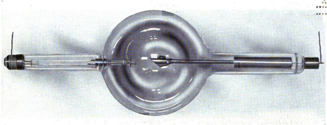
Aside from high-tech synchrotron facilities, most laboratory XAS work is done using X-ray (Coolidge) tube sources. Essentially, this is a high-vacuum tube containing a hot cathode filament (usually tungsten) and an anode surface.
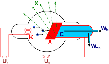
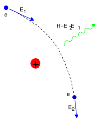
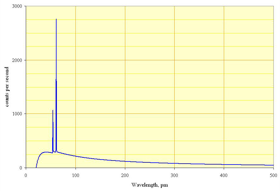
Bremsstrahlung is electromagnetic radiation produced by the deceleration of a charged particle, such as an electron, when deflected by another charged particle, such as an atomic nucleus. The term is also used to refer to the process of producing the radiation. Bremsstrahlung has a continuous spectrum. Brehmsstrahlung is German for “braking radiation”, generated when fast-moving electrons closely approach atomic nuclei and are deflected off their incident trajectory by electrostatic forces. The energy lost to this deflection is emitted in the form of radiation. Since the ΔE due to deflection differs depending on the path of the incident electron, brehmsstrahlung produces an essentially continuous spectrum.
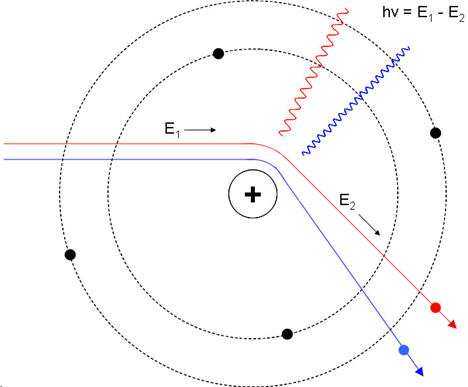
Types of radiation from this: Characteristic output (Resonant transitions from one electron energy level to another) and Bremsstrahlung (inelastic scattering). The former is narrow and the latter is broadband.
Synchrotron radiation
Synchrotron radiation is, very simply, radiation from relativistic charged particles moving in a uniform magnetic field. It is the relativistic equivalent of cyclotron radiation and is named after the relativistic accelerators. Cyclotron radiation is electromagnetic radiation emitted by moving charged particles deflected by a magnetic field. The Lorentz force on the particles acts perpendicular to both the magnetic field lines and the particles' motion through them, creating an acceleration of charged particles that causes them to emit radiation (and to spiral around the magnetic field lines).


Detectors
X-radiation, upon contact with an inert gas atom, can collide with and transfer a massive amount of kinetic energy to an outer electron of the shell, ionizing the gas. The ejected electron, known as a photoelectron, releases its excess kinetic energy by subsequent collisions with other outer shell electrons, causing an ionization cascade. Gas-filled transducers take advantage of this interaction by counting the number of electrons produced and correlating this with the kinetic energy of the original photon.
A general schematic of a gas-filled transducer is shown below. In this case, X-rays enter through a low-absorbance window on the side to ionize argon gas. Argon anions migrate towards the wall of the transducer tube, whereas ejected electrons migrate to the central wire anode. The electrical signal from the anode may then be measured and quantified by the signal processor.

Scintillators are materials which fluoresce (or phosphoresce) in the presence of ionizing radiation. Scintillation counters combine this property with another well-known phenomenon — the photoelectric effect — to convert incident X-radiation into an electrical signal and quantify it.

When an X-ray photon hits the scintillator, its energy is absorbed and promptly reemitted at a different wavelength. The emitted photons are gathered and focused towards the photocathode, where they are absorbed and their energy is used to emit electrons via the photoelectric effect. The photoelectrons are in turn focused towards a series of metal electrodes known as dynodes. When a photoelectron hits the first dynode, its kinetic energy is sufficient to knock several more electrons off the dynode surface via the Auger effect. These Auger electrons proceed through the rest of the dynode series, producing more and more electrons with each impact. Finally, the amplified electron signal is absorbed at the anode, measured, and quantified.