
7.3: Wavelength Selectors
- Page ID
- 220454
Wavelength Selectors
A wavelength selector is a instrument component that either selects and transmits a narrow band of wavelengths emanating from a broad band optical source of transmits one or more lines from a discrete wavelength source. Wavelength selectors come in two types; fixed wavelength or scanning. In either case the main quality characteristics of a wavelength selector are the effective bandwidth and the %transmittance. As shown in Figure 7.3.1, the effective bandwidth is the spread in the wavelengths transmitted around the central wavelength, specifically those wavelengths transmitted in intensities > 50% of the maximum transmittance.

Figure\(\PageIndex {1}\): An illustration of the meaning of the term "bandwidth" for a wavelength selector.
Monochromators
A monochromator is a scanning type of wavelength selector. Originally based on glass or quartz prisms, current monochromators are constructed with holographic diffraction gratings that are produced using the kinds of lithographic techniques used to created computer chips. These holographic diffraction gratings are superior in terms groover regularity and lower amounts of scattered light and to the ruled master and replica gratings of the past.
As shown in Figure 7.3.2, a monochromator consists of an entrance and exit slits, a diffraction grating mirrors to first expand the incoming light to fill the area of the grating and subsequently focus the diffracted light on the exit slit. A grating for the UV and visible regions of the spectrum will between 300 - 2000 grooves per mm (most commonly 1200 to 1400 grooves/mm) and be blazed at an angle where the transmittance is best for the wavelengths of interest. Gratings for the IR where the wavelengths are longer that in the UV and visible will have less grooves /mm.
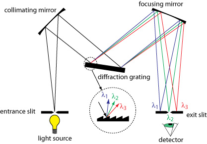
Figure\(\PageIndex {2}\): An illustration of the meaning of the term "bandwidth" for a wavelength selector. Image from the image and video exchange hosted by community.asdlib.org
As shown in Figure 7.3.3, the light diffracted off each facet of the grating can be considered to be emanating from a point source. If we consider two beams of light incident at an angle \({\alpha}\) on adjacent facets spaced at a distance d and the results diffracted beams reflected at angle \({\beta}\), the difference in distance traveled can be shown to be d(sin\({\alpha}\)+sin\({\beta}\)). If this difference in distance traveled is equal to an integral number of wavelengths, n\({\lambda}\), the beams will be in phase with one another and constructively interfere. If the distance is anything other than an integral number of wavelength the beams with destructively interfere with annihilation occurring when the beams are 180° out of phase. For a beam of white light incident at angle \({\alpha}\), constructive interference will occur for different wavelengths different angles of reflection, \({\beta}\). Consequently the light is dispersed along the plane of the exit slit. In practice, a monochromator is scanned by the rotating the grating so that both angle \({\alpha}\) and angle \({\beta}\) are changing and different wavelengths are passed through the exit slit.
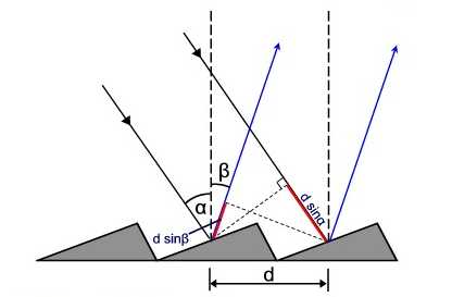
Figure\(\PageIndex {3}\): Each facet of the grating behaves like a point source and for constructive interference the difference in path traveled needs to me an integral number of wavelenghts. Image from the physics.stackexchange.com
The grating described above is called an echellette grating and typically these are used in first order (n=1). Echelle gratings which have many less grooves per mm but are operated in much higher orders are used in instruments for atomic spectroscopy.
For grating based monochromators used at small angle r the linear dispersion of wavelengths is a constant meaning the that distance along the exit slit between where 300 nm light and 400 nm light strikes is the same distance as between 600 nm and 700 nm. The linear dispersion from prism based monochromators is not a constant.
The resolving power or resolution for a monochromator is the ability to separate images that have a slight difference in wavelength and the resolving power improves as the number of grooves of the grating are illuminated, hence expanding the light to fill the area of the grating is advantageous.
The effective bandwidth for a monochromator is the product of the reciprocal linear dispersion, D-1 and the slit with, W. D-1 has units of nm/mm and describes the spread of wavelengths in nm per mm of linear distance along the exit plane of the slit. For most benchtop instruments the slit width, W, is adjustable.
For a 0.5 m focal length monochromator with a 1200 groove/mm grating operated at small angle r and in first order the resolving power at 30 nm is about 60,000 and the D-1 is about 2 nm/mm. Both metrics would improve for a larger monochromator with longer focal length.
Interference Filters
Interference filters are fixed wavelength selectors based on the principle of constructive and destructive interference. Consider the two rays, 1 and 2, shown in Figure 7.3.4. When these two rays strike the first semi-reflective surface some of the light is reflected and some of the light enters the transparent dielectric. The light entering the dielectric is diffracted and travels to the second semi-reflective surface. At this second interface some of hte light is reflected and some of the light is transmitted. Focusing on the internal reflected beam or ray 1, if when this beam combines in phase with beam 2 at the point circled in purple then constructive interference will occur. This condition for constructive interference will be met when the path highlighted in yellow is a distance equal to an integral number of wavelengths of the light in the dielectric material, \(n{\lambda}=2d{\eta}/cos{\theta}\). Thus the central wavelength transmitted by an interference filter is dependent on the thickness and composition of the dielectric layer.
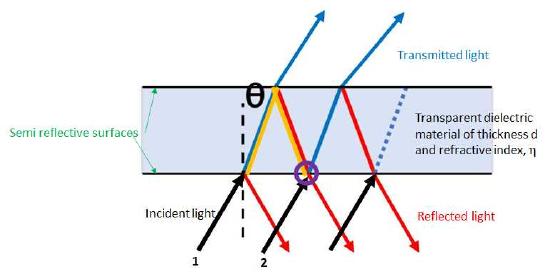
Figure\(\PageIndex {4}\): A sketch of an interference filter where d is the thickness of the dielectric material, \({\eta}\) is the refractive indez and \({\theta}\). is the angle of incidence.
For light incident along the surface normal the angle \({\theta}\) will be zero and the equation simplifies to \(n{\lambda}=2d{\eta}\).
Depicted in Figure 7.3.5 are the transmission profiles of a series of interference filters. As evidenced by figure 7.3.5 the typical bandwidth is on the order of 10 nm or less with the smaller bandwidths, 1 nm, produced by multilayer filters.
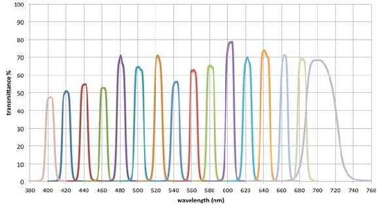
Figure\(\PageIndex {5}\): The transmittance profiles of a series of interference filters covering the visible region of the spectrum. Image taken from Flückiger, Barbara & Pfluger, David & Trumpy, Giorgio & Aydin, Tunç & Smolic, Aljosa. (2018). Film Material-Scanner Interaction.
Shortpass, Longpass and Band Pass Filters
Other filters that find use in analytical experiments include shortpass, longpass and band pass filters. As shown in Figure 7.3.6 these types of filters absorb or reflect large portions of UV or visible regions of the spectrum.
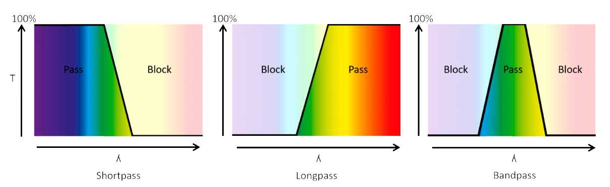
Figure\(\PageIndex {6}\): A series of sketches illustrating the difference between a short pass, long pass and bandpass filter. Image taken from https://www.photometrics.com/learn/microscopy.