13.2: Term splitting in ligand fields, selection rules, Tanabe-Sugano diagrams. Metal to ligand, and ligand to metal transitions
- Last updated
- Save as PDF
- Page ID
- 344605
Term Splitting of Terms in an Octahedral Field
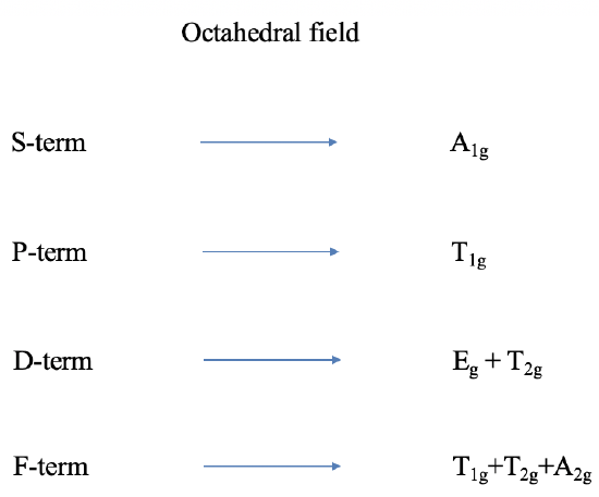
Thus far we have only considered free ion terms, that means terms without the presence of a ligand field. Let us next think about the influence of an octahedral field on a term. Terms are wavefunctions, just like orbitals, and therefore they behave like orbitals in a ligand field. D-orbitals split into t2g and eg orbitals in an octahedral ligand field. A D-term behaves similarly. It splits into T2g and Eg terms. P-orbitals are triple-degenerate having T1g symmetry in the point group Oh and do not split in energy. P-terms have the same symmetry and also do not split. We can call a P-term in an octahedral ligand field a T1g term. Following analogous arguments, S terms become A1g terms. F terms do split in energy like f-orbitals and become T1g, T2g, and A2g terms. Overall, the presence of the octahedral field increases the number of terms from four to seven (Fig. \(\PageIndex{1}\)). It is easy to see that the ligand field leads to many states, and many potential electron transitions. Thus, we would expect quite complicated spectra. For other ligand fields, the terms also behave analogously to orbitals. For, instance in a tetrahedral field D-terms split into E and T2 terms, and so forth.
Term Splitting for octahedral d2 metal complexes
Now let us think about how the term energies of our free d2-ion changes when placed in an octahedral ligand field, depending on the ligand field strength. We can express this by a correlation diagram (Fig. 8.2.2). In a correlation diagram, we plot the energies of the terms relative to the field strength.
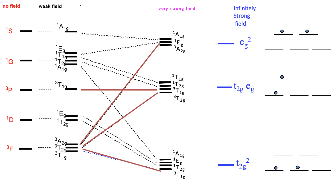
On the left side we plot the terms without any field according to their energies. In the case of a d2 ion, the energies are 3F<1D<3P<1G<1S. Next, we plot the relative energies in a weak octahedral ligand field, and label the terms according to their symmetry. We can see that the D, F, and G terms split in energy, while the S and P terms do not. Because of the weak field, energy differences are very small. Now let us increase the ligand field strength continuously, until we have reached a very strong ligand field. We see that some of the terms move up in energy, while other terms move down as the ligand field increases. For example, two of the three terms resulting from the F-terms increase in energy while one decreases. It is also possible that a term does not change its energy. For example, the 3T1g term from the 3P term does not change its energy. In very strong ligand field there are three groups of terms that have similar energy. In the hypothetical case of an infinitely strong ligand field, the terms that belong to a particular group become identical in energy. In this case, there are only three states for the electrons possible. The field is considered so strong so that the energy associated with electron-electron interactions become negligible compared to the energy of the field. The electrons behave as though there were no electron-electron interactions. Therefore, we can call the lowest energy state the t2g2 state. It is equivalent to the state of the two electrons being in the t2g orbitals. The second state is called the t2geg state. It is equivalent to the state of one electron being in the t2g and one electron being in the eg orbitals. The third state is called the eg2 state, which is equivalent to the state with both electrons in the eg2-orbitals.
Selection Rules
In most cases, the ligand field strength is in between the very weak and very strong case, and thus, we could expect very complicated spectra. Fortunately, nature does not make things quite as complicated, because not all possible electron transitions are quantum-mechanically allowed. The allowed transitions are defined by two rules: The spin selection rule and the Laporte rule.

The spin selection rule states that only transitions are allowed in which the total spin quantum number S does not change. When S does not change also the spin multiplicity does not change. Thus, electron transitions are only allowed for transitions that do not involve a change in spin multiplicity. For example, it would be allowed to excite an electron from a triplet term to another triplet term, but not from a triplet term to a doublet or singlet term.

The Laporte rule state that transitions are only allowed when there is a change of parity. This means a transition from a gerade (g) to an ungerade (u)-term and vice versa is possible, but not a transition from a g-term to another g-term, or the transition from a u-term to another u-term. For example, the transition from a T2g to a T1u term would be allowed, but not the transition from a T2g to a T1g term.
Tanabe-Sugano diagram of a d2 octahedral complex
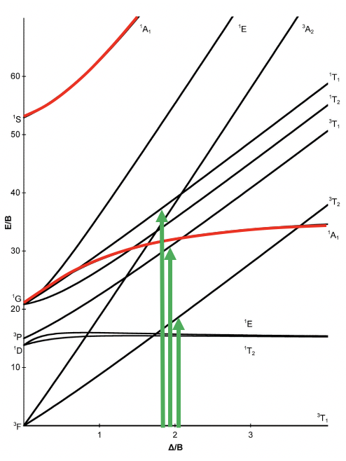
A particular correlation diagram is the Tanabe-Sugano diagram (Fig. 8.2.3). It is illustrated here for an octahedral d2 complex. The difference to the previously discussed correlation diagram is that the energy of the ground state is plotted horizontally, and the energy of all other terms are plotted relative to that. In the case of the d2 electron configuration, the 3T1g term is the ground term and is plotted as a horizontal line. We can see that the ligand field strength on the x-axis is given in units of B, and the energy of the terms is also given in units of B. B is a so-called Racah parameter, that is a quantum-mechanical energy unit for the electromagnetic interactions between the electrons. It is chosen because it provides “handy” numbers.

You can see that some lines in the diagram are bent, and some are straight. Bending of lines occurs when two terms interact with each other because they are close in energy and have the same symmetry. This is again an analogy to orbitals. Like orbitals interact when they have the same symmetry type and similar energy, also terms interact when they have the same symmetry and the similar energy. Without taking their interactions into account, their energies can cross when the energy of term A declines and the energy of term B increases with increasing field strength (Fig. 8.2.4). The closer the terms come to the point where they cross, the stronger their interactions, because their energies become more and more similar. The interactions lead to the fact that the terms "bend away" from each other, leading to bent curves. This means that curves for two terms of the same symmetry type will bend away in a Tanabe-Sugano diagram and never cross. For example the terms for the two 1A1g terms bend away from each other and do not cross.
Next, let us think about which electron transitions would be allowed under the consideration of the spin selection and the Laporte rule. We notice that in the symmetry types the “g” for gerade has been omitted (Fig. 8.2.3). This is a common simplification made in the literature. We have to remind us that all the terms in the diagram are “g” terms. What does this mean for the allowance of electron transitions? It means that no electron transition would be allowed, and that would imply that the complex could not absorb light. The Laporte selection rule however does not hold strictly. It only says that the probability of the electron-transition is reduced, however, not forbidden. This means that an absorption band that disobeys the Laporte rule will have lower intensity compared to one that follows the Laporte rule, but it can still be observed. The spin-selection rule, however, holds strictly, and transitions between terms of different spin multiplicity are strictly forbidden, meaning that they have near zero probability to occur. Overall, we can therefore excite an electron from the 3T1 ground state to other triplet terms, namely the 3T2 term, and the 3A2 term (Fig. 8.2.3).
Tanabe-Sugano diagram of d3 octahedral complexes
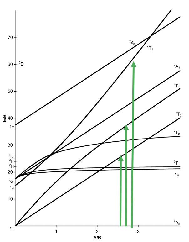
Now, let us have a look at the Tanabe-Sugano diagram of a d3 ion in an octahedral ligand field (Fig. 8.2.7). What is the ground term? We can see the term designation on the horizontal line reads “4A2”, therefore this term is the ground term. How many electron transitions from the ground state should we expect? To answer this question we need to count the number of other quartet terms. There is the 4T2, the 4T1, and another 4T1. Thus, there are overall three electron transitions possible. Can we understand why the ground state is a quartet term?
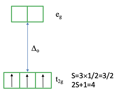
It helps to consider how we would fill the electrons into the d-orbitals for the electron configuration d3. All three electrons would be filled spin-up in the t2g orbital following Hund’s rule (Fig. 8.2.8). Because each electron has the spin +1/2 the total spin of all three electrons is 3x1/2=3/2. Thus, the spin multiplicity is ((3x3/2)+1)=4. Note that the microstate we have drawn is actually only one of the (2L+1)(2S+1) microstates. S=3x1/2=3/2, but what is L? You can see one the left side of the diagram that the 4A2 term originated from a 4F term. This means L=3, and (2L+1)((2S+1)=7x4=28. This means that there are actually 27 other microstates that have the same energy as the microstate that we drew. Why did we draw this microstate in favor of the others? This is because this microstate is the state with the maximum ML (=L) and Ms (=S) values determining the term symbol.
Tanabe-Sugano diagram of d4 octahedral complexes
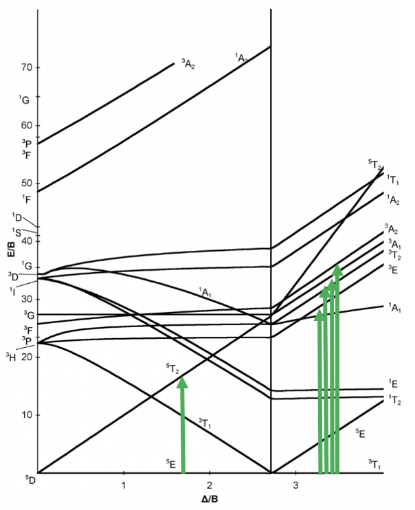
Now let us look at the Tanabe-Sugano diagram of a d4 octahedral complex. You can see that this diagram is separated into two parts separated by a vertical line. The line indicates the ligand field strength at which the complex changes from a high spin complex. At lower ligand field strengths, the ground term is a 5E term. At higher field strength the ground term is a 3T term.
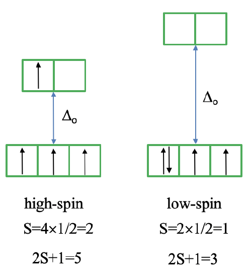
We can rationalize this again by drawing the orbital box representation of the d-orbitals in the octahedral ligand field. In the high spin state, there are four unpaired electrons, thus S=4x1/2=2, and 2S+1=5. In the low spin state, there are two unpaired electrons, and thus S=2x1/2=1, and 2S+1=3. This explains the quintet and the triplet nature of the high and low spin ground terms. Note again, that the two microstates represented by the orbital box diagrams (Fig. 8.2.10) are not the only microstates that have the respective energy. They are only the "representative" microstates because the have the maximum ML and MS values.
How many electron transitions are possible from the ground term? For a high spin complex there is only one because the is only one other quintet term, namely the 5T2 term. For the low spin complex, there are five transitions because there are five other triplet terms.
Tananbe-Sugano diagram of d5 octahedral complexes
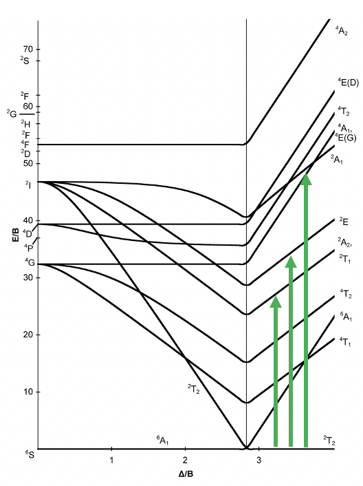
Also the Tanabe-Sugano diagram of a d5 octahedral complex is divided into two parts separated by a vertical line (Fig. 8.2.11). The left part reflects the high spin and the right part the low spin complex.
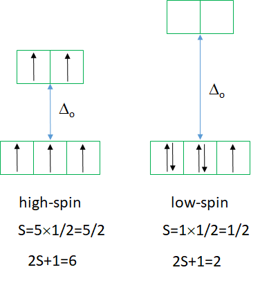
The high spin ground state is a sextet term, and the low spin ground state is a doublet term. We can understand the sextet and doublet nature of the terms when considering that the associated electron box diagram have five and one unpaired electrons respectively. S=5x1/2=5/2 and 2S+1=6 for the high spin term, and S=1x1/2=1/2 and 2S+1=2 for the low spin term. What are the possible electron transitions from the ground state? For the high-spin complex there is no other sextet term, meaning that there is no electron transition possible. Hence, high-spin octahedral d5-complexes are colorless. An example is the hexaaqua manganese (2+) complex. A solution of this complex is near colorless, only very slightly pinkish. The slight color is because also spin-forbidden transitions can occur, albeit at a very low probability. For a d5-low spin complex there are three additional doublet states, and thus there are three electron transitions possible.
Tanabe-Sugano diagram of d6 octahedral complexes
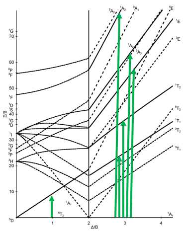
The next diagram is the one for the d6 electron configuration (Fig. 8.2.13). Again, the diagram is separated into parts for high and low spin complexes. You can see dotted lines in the diagram. They indicate the terms that have a different spin multiplicity than the ground term. This way we can more easily see how many electron transitions are allowed.
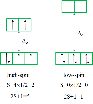
The ground term for the high-spin complex is the quintet 5T2 term. It is a quintet term because four electrons in the d-orbitals are unpaired, and two are paired. The value for S is thus 4x1/2=2, and the spin multiplicity is 2S+1=5. The ground term for the low spin complex is a 1A1 term. It is a singlet term because all electrons are paired, and thus S=0, and 2S+1=1. How many electron transitions are there for the high-spin complex? There is only one because the 5E term is the only other quintet term. There are five transitions possible for the low-spin case because there are five additional singlet terms.
Tanabe-Sugano diagram of d7 octahedral complexes
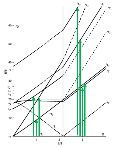
Next, let us look at the Tanabe-Sugano diagram of a d7 octahedral complex (Fig. 8.2.15). In this case, the high spin complex has a 4T1 ground term, and the low spin complex has a 2E ground term.
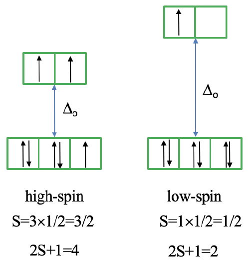
The microstate that "represents" the high spin ground term has three unpaired electrons, hence the spin quantum number S=3/2 and the spin multiplicity is 2S+1=4. The microstate that represents the low spin ground term has one unpaired electron, an S value of ½, and a spin multiplicity of 2. There are three other quartet terms, and four other doublet terms, hence there are three electrons transitions for the high-spin complex, and four for the low spin complex.
Tanabe-Sugano diagram of d8 octahedral complexes
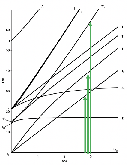
Now let us look at an octahedral complex with d8 electron configuration. For this electron configuration, there are no high and low spin complexes possible, therefore, the Tanabe-Sugano diagram is no longer divided into two parts (Fig. 8.2.17).
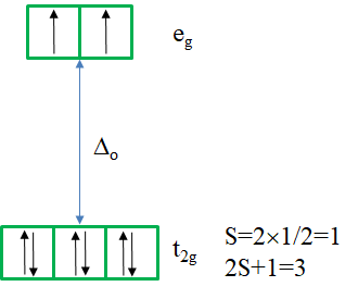
There is a single ground term of the type 3A2. It is a triplet state because the microstate representing the term has two unpaired electrons in the eg orbitals (Fig. 8.2.18). Thus, S=2x1/2=1, and the spin multiplicity is 2S+1=2. How many electron transitions would you expect? There are three other triplet states, namely the 3T2 and two 3T1 terms. Therefore, there are three electron transitions possible.
We could also ask: Are there Tanabe-Sugano diagrams for d1, d9, and d10? For, d1 there are no electron-electron interactions, thus the simple orbital picture is sufficient. The 2D term splits into T2g and Eg terms, and there is only one electron transition possible. The d9 electron configuration is the “hole-analog” of the d1 electron configuration. It has also just one 2D term which splits into a T2g and an Eg term in the octahedral ligand field. Therefore, also in this case there is only one electron transition from the T2g into the Eg term possible. In the case of d10 all microstates are filled with orbitals, and there is only the 1S term which does not split in an octahedral ligand field. Therefore, there are no electron transitions in this case.
Finally, it should be mentioned that it is also possible to construct Tanabe-Sugano diagrams for other shapes such as the tetrahedral shape, but we will not discuss these further here.
Charge Transfer Transitions
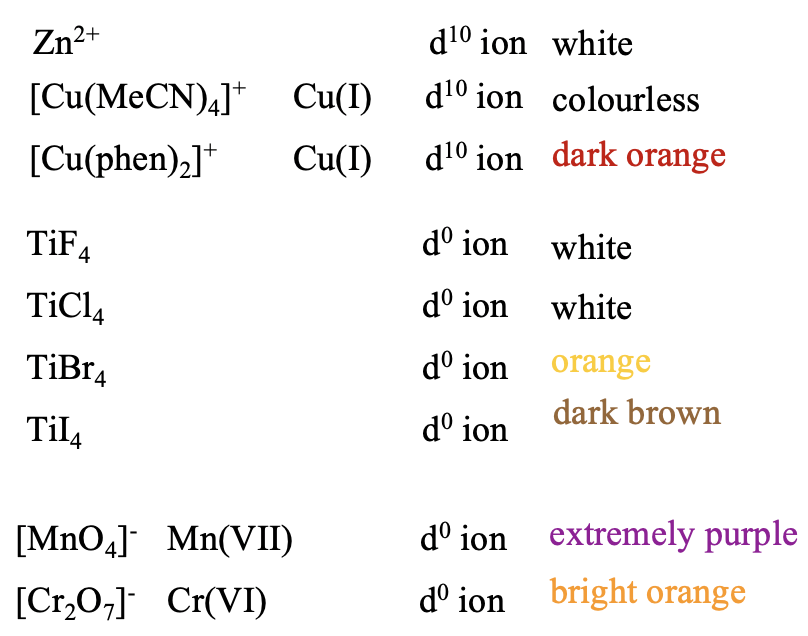
We are still not done with our electronic spectra. Thus, far we have only considered transitions of d-electrons between d-orbitals, and their terms. They are called d-d transitions. However, there are also so-called charge transfer transitions possible, that are not d-d transitions. We can easily see that there must be other transitions but d-d transitions when we look at the color of d10 and d0 ions. For those, the are no d-d transitions possible. Therefore, they all should be colorless. However, that is not always true. Some of these ions are indeed colorless, but some are not (Fig. 8.2.19). For example, Zn2+, a d10 ion is colorless in complexes, but not Cu(I) which is also d10. While tetrakis(acetonitrile)copper (+) is colorless, bis(phenanthrene) copper(+) is dark orange. Similar is true for d0 ions. While TiF4 and TiCl4 are colorless, TiBr4 is orange, and TiI4 is brown. Some d0 species are even extremely colorful, for example permanganate with Mn7+ which is extremely purple, and dichromate with Cr(VI) which is bright orange.
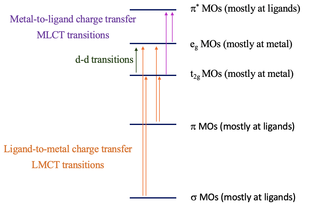
The explanation of these phenomena are charge-transfer transitions (Fig. 8.2.20). There are two types of charge-transfer transitions, the ligand-to-metal (LMCT) and the metal-to-ligand (MLCT) charge transfer transitions. For the ligand-to-metal transitions, electrons from bonding σ and π-orbitals get excited into metal d-orbitals in the ligand field, for example the t2g and the eg orbitals in an octahedral complex. If the energy difference between the σ/π-orbitals and the d-orbitals is small enough, then this electron-transition is associated with the absorption of visible light. The transition is called a ligand-to-metal transition because the ligand σ/π-orbitals are mostly located at the ligands, while the metal-d-orbitals in a ligand field are mostly located at the metal. Vice versa, the metal-to-ligand transition involves the transition of an electron from metal d-orbitals in a ligand field to ligand π*-orbitals. This essentially moves electron density from the metal to the ligand, hence the name ligand-to-metal-charge transfer transition. If the energy-difference between the ligand π* and the metal orbitals is small enough, then the absorption occurs in the visible range. Charge-transfer transitions are usually both spin- and Laporte allowed, hence if they occur the color is often very intense. How can we distinguish between d-d and charge transfer transitions? Charge transfer transitions often change in energy as the solvent polarity is varied (solvatochromic) as there is a change in polarity of the complex associated with the charge transfer transition. This can be used to distinguish between d-d transitions and charge-transfer bands.
LMCT Transitions
Can we predict when the energy windows between the bonding molecular orbitals and the metal d-orbitals are small enough so that LMCT transitions in the visible can take place? Generally, it would be desirable if the energy of the metal orbitals was as low as possible and the energy of the bonding ligand orbitals are as high as possible. The energy of metal d-orbitals decreases with increasing positive charge at the metal because the effective nuclear charge on the metal increases. This means that very high metal oxidation states favor an LMCT transition. The d-orbitals should have few or no electrons, so that electrons can be promoted into the orbitals, and orbital energy decreases because electron-electron repulsion is minimized. Examples are Mn(VII), Cr(VI), and Ti(IV). The energy of MOs from bonding ligand orbitals increases when the ligand orbitals have high energy this is typically the case for π-donor ligand with negative charge (Fig. 8.2.21).
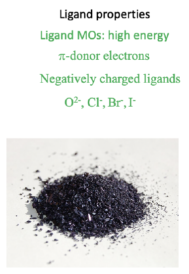
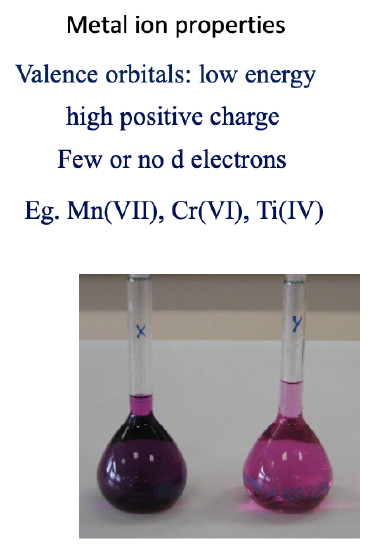
Examples of ligands are oxo- and halo ligands. This explains for example the LMCT transitions in permanganate. The Mn is in the very high oxidation state +7, and the ligands are are oxo-ligands wich are π-donors with a 2- negative charge. The transitions are both Laporte and spin-allowed leading to very high intensity of light absorption, and thus color (Fig. 8.2.21).
MLCT Transitions
What are favorable metal ion and ligand properties for a metal-to-ligand transition, then? In this case we would like to keep the energy of the metal orbitals as high as possible so that the energy difference between a metal d-orbital and a π*-orbital is minimized. This is accomplished when the positive charge at the metal ion is small, and there are many d-electrons that can repel each other, thereby increasing orbital energies, for examples Cu(I), Fig. 8.2.22.
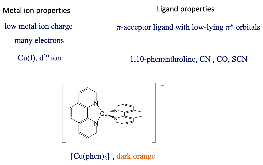
The ligand should be a π-acceptor with low-lying π*-orbitals, for example phenanthroline, CN-, SCN-, and CO. For instance, the bis(phenanthroline) copper(+) is dark-orange and has a MLCT absorption band at 458 nm. Also, the MLCT transfer is both spin and Laporte-allowed.
It should be mentioned that some complexes allow for both metal-to-ligand and ligand to metal transitions. For example, in the Cr(CO)6 complex the σ-orbitals are high enough and the π*-orbitals are low enough in energy to allow for light absorption in the visible range. Finally, also intraligand bands are possible when the ligand is a chromophore.
Dr. Kai Landskron (Lehigh University). If you like this textbook, please consider to make a donation to support the author's research at Lehigh University: Click Here to Donate.


