5.3: Coordination Numbers and Structures
- Last updated
- Save as PDF
- Page ID
- 344591
Coordination Numbers (CN) and Structures of Complexes
Coordination compounds have many different structures or shapes, and therefore it is important that we are able to categorize the structures of coordination compounds, understand why a particular structure forms, and why certain structures are more common than others.
A central parameter that determines the structure is the coordination number. A coordination number is the number of points of attachment between the ligands and the metal.
Definition: Coordination Number
The coordination number is the number of points of attachment between the ligands and the metal
What are the main factors that are associated with the coordination number? Some of them are associated with the metal ion, and some of them are associated with the ligands. The shape and the size of a ligand greatly influences the coordination number. Generally, the bulkier the ligand the smaller than coordination number. With regard to the metal ion, the size of the metal ion plays an important role. The larger the metal ion, the more ligands fit around it, and the coordination number increases. In addition, the electron configuration of the metal ion plays a role. For certain electron configurations certain coordination numbers are preferred because these coordination numbers stabilize electron energies. Lastly, there are intermolecular interactions to consider. In solid state they occur between neighbored complexes, in solution they occur between the complex and solvent molecules. This can lead to different coordination numbers and structures in the solid state, and in solution, respectively.
Main Factors Determining CNs
- Shape and size of ligands
- Size of metal ion
- Electron configuration of metal ion
- Intermolecular interactions (solution vs. solid state)
As you can see, there are many factors that influence the coordination number, and the shape of the complexes. These factors are sometimes opposing, which makes the prediction of structures difficult. Nonetheless, there are a number of rules that allow for a fair accuracy in structure prediction, and we will go through these rules in the following.
Low Coordination Numbers (CN)
CN = 1
The coordination number 1 is very rare. When there is one point of attachment, then there are usually reactive coordination sites at the metal ion that lead to cluster formation. This reduces the energy and increases the coordination number. For example, in methyl lithium (MeLi) the Li appears to have the coordination number 1 because you may think that there is only a single, covalent Li-C bond. However, there is actually a tetrahedral cluster Li4Me4.
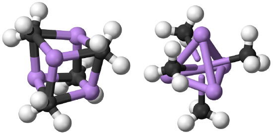
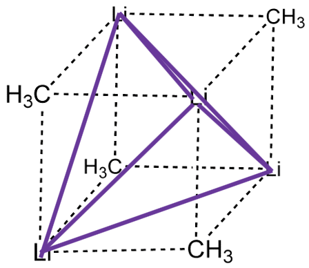
The four Li atoms build a tetrahedron and the methyl groups are placed above the faces of the tetrahedron (Fig. 5.3.1). One can also think of MeLi as a near cubic molecule in which the Li atoms occupy every other vertice of the cube, and methyl groups the remaining vertices of the cube (Fig. 5.3.2). The cluster formation avoids the coordination number 1, and stabilizes the methyl lithium. In addition to a tetrameric cluster there is also a hexameric cluster for Me-Li known.
.
The coordination number 1 is only possible when a large metal ion is surrounded by a very bulky ligand that suppresses cluster formation, and there is no coordination of solvent molecules to the metal.
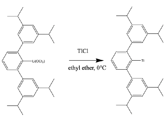
An example the the cluster 2,6,-Trip2C6H3Tl. (Trip = 2,4,6, i-Pr3C6H2), Fig. 5.3.3. It has a Tl+ coordinated to a bowl-shaped, bulky ligand via a Tl-C bond. The Tl fits exactly into the bowl-shaped cavity in the ligand, thereby preventing cluster formation. The compound can be prepared from its lithium derivative and thallium chloride in diethyl ether at 0°C.
CN = 2
The coordination number 2 is also rare, but already a lot more common than the coordination number 1. Generally, d10 metal ions have a tendency to make structures with CN=2. These structures are linear structures. An example of a d10 ion is Ag+. Why is it d10? Ag is located in group 11, so it has 11 valence electrons. If we remove one, there are ten. The energy of the Ag+ ion is minimized when the 4d-subshell is full, and the 5s-subshell is empty. Ag+ makes many linear structures with ligands, example ammine ligands or cyano ligands. In an oversimplified picture, we may explain the structure using VSEPR arguments assuming there is an sp-hybridization of the 5s and one 5p orbital, and the two electron lone pairs at the two ligands get donated into the sp-hybridized orbitals. What other d10-ions can you think of? There would be the higher and lower homologue of the Ag+ ion, the Cu+, and the Au+ ion.
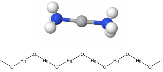
They make linear complexes such as CuCl2- and Au(CN)2-. Hg2+ is also a d10 ion that often makes linear complexes, for example Hg(CN)2-. This linear coordination is not only found in molecular compounds but also in extended solids. For example, HgO and HgS make zig-zag chains of linearly coordinated Hg2+ (Fig. 5.3.4). The bending of the chain occurs at the oxide anions, because of the electron lone pairs at O. Other metal ions but d10 ions make linear structures only when the ligands are very bulky. These examples are rare.
CN = 3
The coordination number 3 is also rare for coordination compounds. They are most common for d10 ions, especially when the ligands are bulky. In most cases the trigonal planar structure, or a structure close to that is adopted.
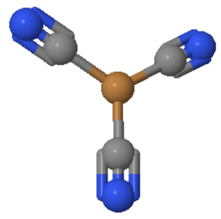
An example is the Cu(CN)32- anion in which Cu+ is surrounded by three cyanide anions in a trigonal planar fashion (Fig. 5.3.5).
CN = 4
The coordination number 4 is a very common coordination number. It is actually the second-most common coordination number, only surpassed by the coordination number 6. The by far most common structure associated with the coordination number 4 is the tetrahedral structure. Why? It is because the ligands have the greatest distance from each other, and the smallest steric repulsion. Generally, smaller ions and/or larger ligands favor the coordination number 4 over the coordination number 6.
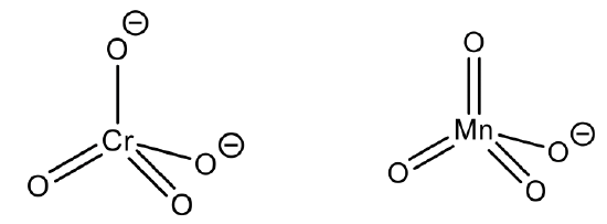
This is the case in the permanganate anion and the chromate anion, for example. Here, the oxidation state of Mn and Cr are +7 and +6 respectively, making the ionic radius very small.
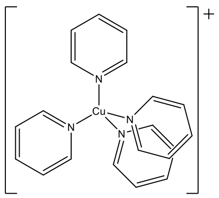
Another example is the tetrakis(pyridyl) copper(1+) ion. Here, the ligands are fairly bulky. The tetrahedral structure is particularly common for d0 and d10 ions, and mostly favored over the octahedral structure. All examples above have either d0 or d10 ions. Cr(VI) and Mn(VII) are d0 and Cu(I) is d10 thus fulfilling this requirement as well.
The second-most common structure after the tetrahedral structure is the square planar structure. It is only common for ions with d8 electron configuration. What are common d8 ions? Examples are the ions Ni2+, Pd2+, and Pt2+. We can find these elements in group 10 of the periodic table. Therefore, they must have ten valence electrons in the neutral state. Because of the 2+ charge, two electrons are removed leaving eight electrons. All eight electrons are in the d-valence subshell, therefore the ions are called d8 ions.
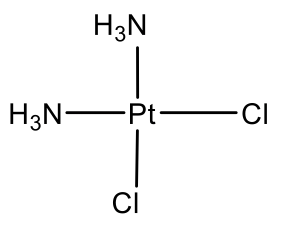
The arguably most well known square planar complex is cis-platinum. It has two chloro and two ammine ligands attached to Pt in cis-position. It is known as anti-cancer drug.
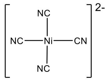
Ni(CN)42- is another example of a group 10 square planar complex.
Can you think of other d8 ions? The group 11 elements Cu, Ag, and Au have eleven valence electrons in the neutral state. In this case we need to remove three electrons to get to eight electrons, meaning that Cu3+, Ag3+, and Au3+ are d8 ions. Cu and Ag are not very stable in the oxidation state +3, therefore examples of square planer Cu(III) and Ag(III) are fairly rare.
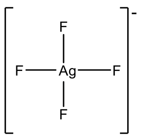
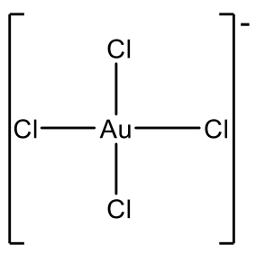
Examples are AgF4- and CuF4-, Fig. 5.3.10. However Au3+ is more common and there is a relatively large number of Au(III) complexes, e.g. AuCl4-.
Because group 12 elements are not stable in the oxidation state 4, there are no group 12 d8 ions. However group 9 d8 ions are known. In this case the ions must be in the oxidation state +1 in order to have eight d electrons. Cobalt is not stable in the oxidation state +1, but Rh and Ir are, and square planar Rh(I) and Ir(I) complexes are common.
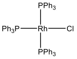
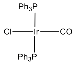
For example Rh makes a Rh(PPh3)3Cl complex (Fig. 5.3.11). It is a common hydrogenation catalyst. Vasca’s complex Ir(CO)(PPh3)2Cl is another example (Fig. 5.3.11). It has the property to reversibly bind oxygen.
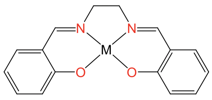
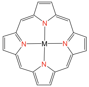
The square planar coordination is possible also with metal ions other than d8 ions, but only when the ligand forces the metal ion into this coordination. Ligands that do this are for example the porphyrin ligand and the salen ligand. They are tetradentate ligands with donor atoms that form a square forcing the metal ion to adopt a square-planar coordination (Fig. 5.3.12).
A last possibility is the seesaw structure. It is know for main group elements, but not for transition metal elements.
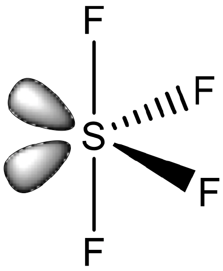
An example is SF4 (Fig. 5.3.13). The seesaw structure is derived from the octahedral structure whereby two adjacent corners of the octahedron are occupied by electron lone pairs. Formally one could consider a compound like SF4 as a coordination compound in which four F- ligands bind to an S4+ cation. However, this view is commonly not adopted, and the S-F bonds are not viewed as dative covalent bonds.
CN = 5
For the coordination number 5, the two most common structures are the trigonal bipyramid and the square pyramid. They are about equally common because they have very similar energies. Which one is preferred, depends on the particular circumstances, the nature of the metal, the ligands, the solvent, etc. Many molecules have structures in between, mostly described as distorted trigonal bipyramids. Distortion is even more common in solid state due to packing effects. Packing effects minimize the void space in the crystal.
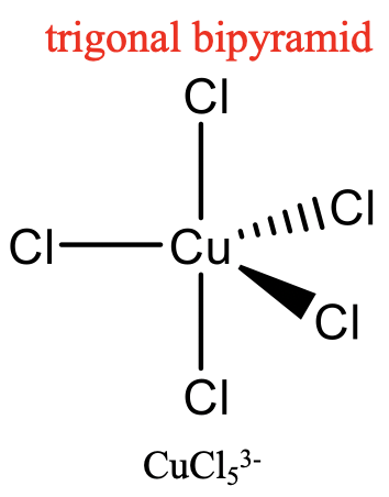
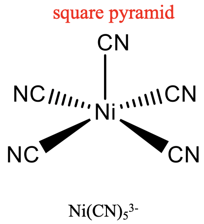
An example for a trigonal bipyramidal structure is CuCl53-, an example for a square-pyramidal structure is Ni(CN)53- (Fig. 5.3.14). The pentagon, another conceivable structure, is not known. Five-coordinate compounds are known for the full range of transition metals. A difference compared to the structures with the coordination numbers 2 to 4 is, that in the structures with the coordination number 5 not all ligands are symmetry-equivalent. For the trigonal bipyramidal shape we distinguish between axial and equatorial ligands. In square-pyramidal complexes, the fifth ligand at the tip of the pyramid is symmetrically different to the other four at the base of the pyramid.
Because the energy difference between the trigonal bipyramidal and the square pyramidal structure is small, and there is only a small activation barrier between the two structures, they are often fluxional. This means that they can dynamically interconvert.

This interconversion occurs according to a mechanism called the Berry pseudo rotation. In the Berry pseudo-rotation one 120° bond angle between two ligands in equatorial position increases until it is eventually 180°. The initial 180° angle between two ligands in axial position decreases until it is 120°. This means that the two previously equatorial ligands are now axial ligands, and the two axial ligands are now equatorial ligands. As the Berry pseudo rotations occurs, the complex moves from a trigonal bipyramidal structure through a square-pyramidal intermediate to another trigonal bipyramidal structure. The Berry pseudo rotation happens often very fast, therefore in many measurements the five ligands appear identical. For example, the PF5 molecule shows only one signal in the 19F NMR because the movement of F atoms from the equatorial to the axial position and vice versa is too fast for the NMR time scale. At low temperatures, the Berry pseudo rotation may be slow enough so that axial and equatorial positions can be resolved. In compounds with larger ligands the pseudo rotation may also be slow enough so that axial and equatorial positions are resolved in the NMR.
CN = 6
The most common coordination number is the coordination number 6. This coordination number exists for all transition metal electron configurations from d0 to d10. We can explain this by the fact that many metal ions have the right size to support six ligands around them, and there are many ligands that have the right size to surround a metal ion in the coordination number 6. The by far most common shape for the coordination number 6 is the octahedral shape. It is the shape for which the ligands have the largest distance from each other thereby minimizing steric repulsion. A second reason is that the orientation of atomic orbitals supports the octahedral shape, as many orbitals point along the x,y, and z axes, in particular the p orbitals, and the dz2 as well as the dx2-y2.
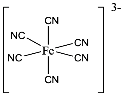
An example is the hexacyanoferrate(3-) anion in which six cyano ligands surround the metal ion octahedrally (Fig. 5.3.16).
Distortions of Complexes with CN = 6
Octahedral complexes can distort in two basic ways. The first common distortion is the so-called tetragonal distortion. Tetragonal distortion can be achieved either via elongating an octahedron along two opposite vertices, or compressing the octahedron along two opposite vertices.
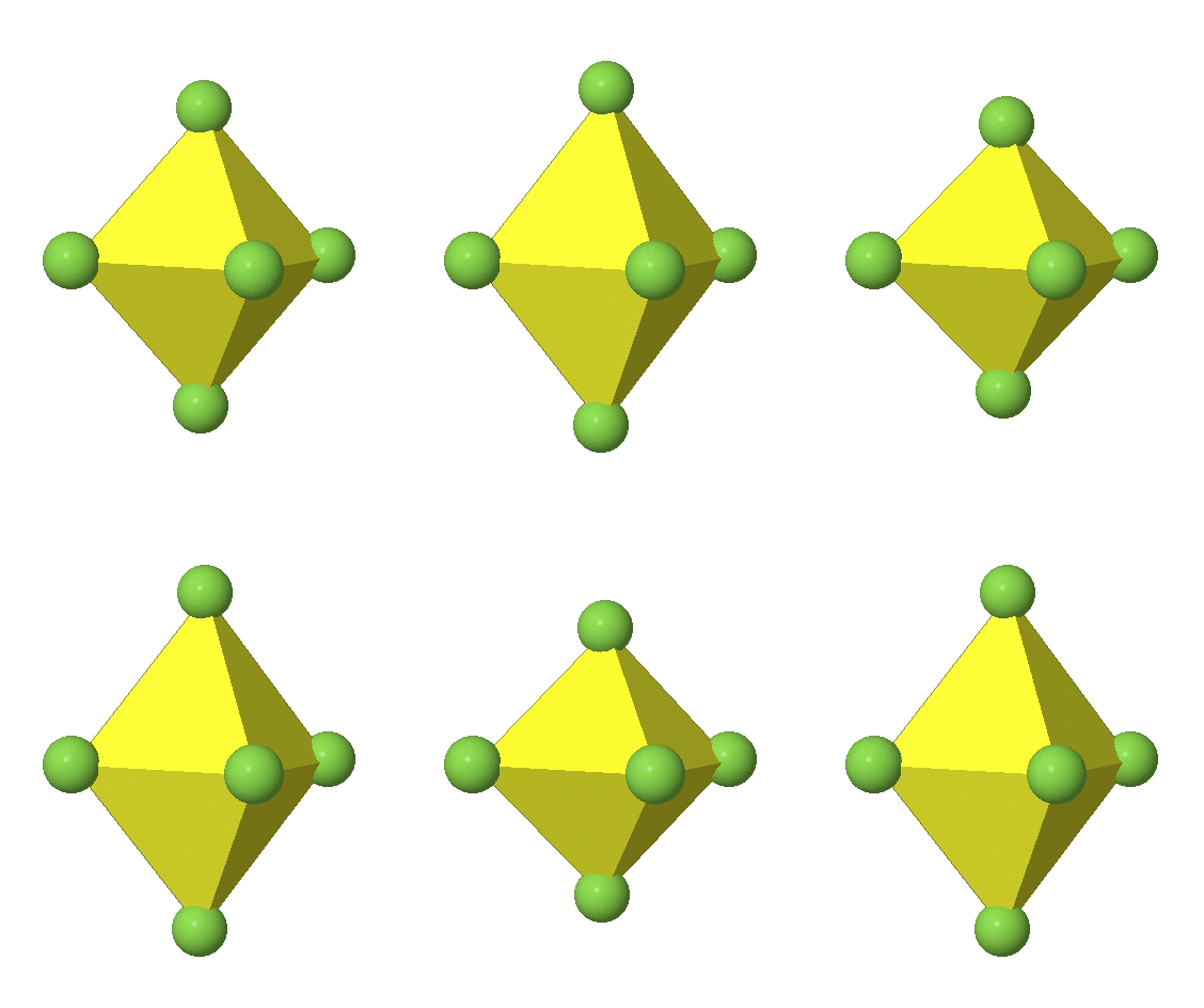
In the first case, two opposite vertices are further away from the center of the octahedron compared to the other four corners (Fig. 5.3.17).
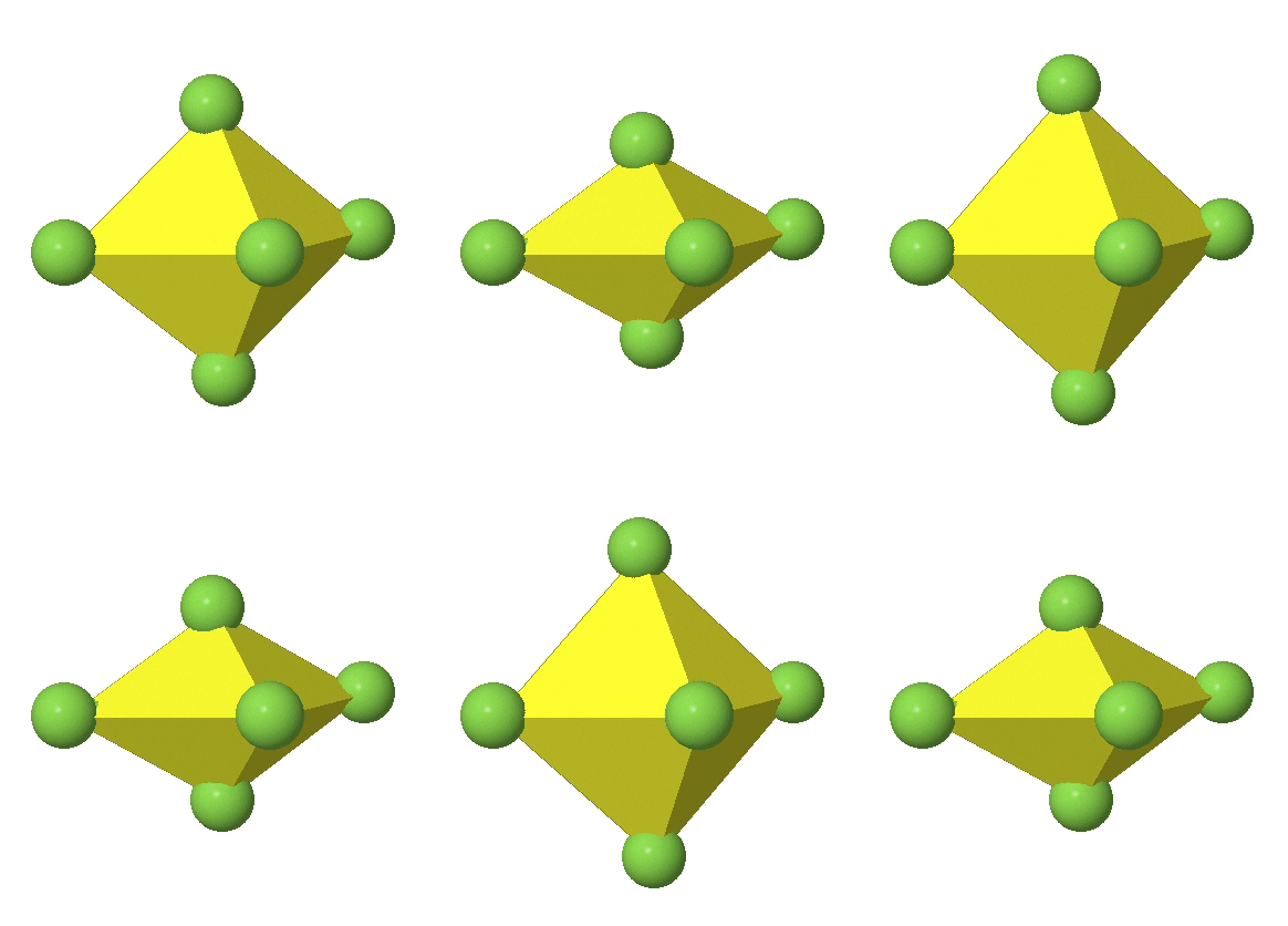
In the compressed octahedron two opposite corners are closer to the center compared to the four other corners (Fig. 5.3.18). Both the elongated and the compressed octahedron have the same symmetry, meaning they belong to the same point group. Which point group is it? We still have a C4 principal axis, but one only. It goes through the corners of the two opposite vertices along which we distorted. There is a horizontal mirror plane perpendicular to the C4 axis, as well as an inversion center. Thus, the point group must be D4h. In tetragonally distorted octahedra all faces are equivalent, but the distances of the ligands from the center of the octahedron are not the same.
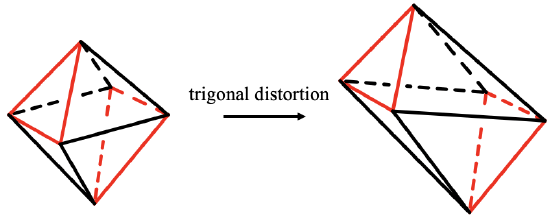
When you elongate or compress the octahedron along to opposite faces you create a trigonal antiprism (5.3.19). It is called antiprism because the two opposite regular triangular faces, shown here in red are oriented in staggered fashion. This type of distortion is called trigonal distortion. The point group of a trigonal antiprism is D3d. The C3 axis goes through the two opposite regular triangular faces of the antiprism. There are three C2 axes standing perpendicular, and going through the centers of the six remaining distorted triangular faces. There are three vertical mirror planes also that bisect the angle between the C2 axes. In a trigonal antiprism the faces are not all equal, but the distance of the vertices are all the same.
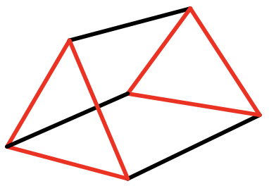
When we rotate one of the two opposite triangular faces of an antiprism by 60°, the two faces become eclipsed and a trigonal prism results (Fig. 5.3.20). Trigonal prismatic compounds are mostly observed when there are three bidentate ligands connecting the top and bottom triangular faces. What is the point group? It is D3h. There is a C3 axes going through the two opposite triangles. 3 C2 axes are going through the centers of the three rectangles, and there is a horizontal mirror plane perpendicular to the C3 axis. Does an elongation or compression along the two opposite triangular faces change the symmetry? Think about it. No, it does not change it.
CN = 7
Coordination numbers higher than 6 are considered high coordination numbers. They are significantly less common than the coordination numbers, 4, 5, and 6. A simple explanation is that large coordination numbers require a very large cation or a very small anion of the combination of both to avoid steric repulsion. These conditions are statistically less likely. In addition, large coordination numbers are not so favorable from the stand point of orbital orientation.
Let us first look at the coordination number 7 in more detail. There are three structures possible which are about equally common in nature.
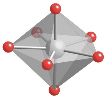
The first one is the pentagonal bipyramid of which ZrF73- is an example (Fig. 5.3.21).
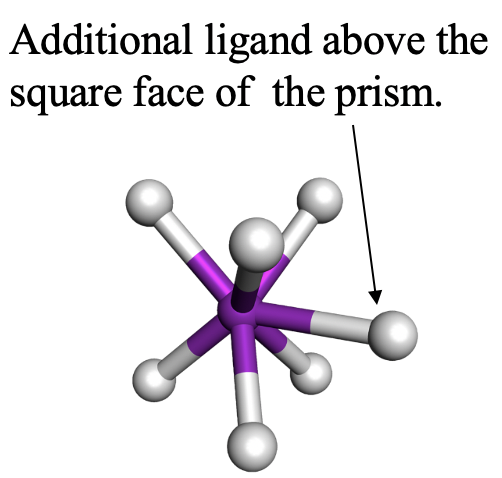
The second one is the capped trigonal prism. TaF72- is an example for it (Fig. 5.3.22). The seventh ligand is placed above a square face of the prism, not a triangular face. Can you imagine why? Think about it for a moment. The answer is that the square face is larger than the triangular face, and thus there is less steric repulsion.
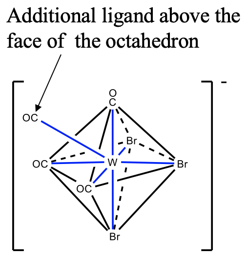
The third structure is the capped octahedron. An example is the tribromotetracarbonyltungstate(IV). In this compound three bromo ligands and three carbonyl ligands occupy the vertices of two opposite faces in the octahedron. The fourth carbonyl ligand is placed above the triangular face with the carbonyl ligands. You can see that like for the coordination number 5, the ligands are not symmetrically equivalent.
CN = 8
Now, let us go to the coordination number 8. What shapes could you imagine that adopt the coordination number 8? The most symmetric, and simple shape is the cube (Fig. 5.3.24).
Figure 5.3.24 Transformation of a cube into a square antiprism. No cubic complexes are known.
However, complexes with cubic shapes are not observed. This is because there is another related structure which is energetically more favorable. It is the square antiprism (Fig.5.3.25). In a square antiprism, two opposite square faces are oriented in staggered fashion relative to each other. Relative to the cube one face of the cube is rotated by 45° relative to the opposite face, and the two opposite square faces are interconnected with each other to form triangular faces. The square antiprism is preferred over the square prism because the vertices where the ligands sit have a greater distance to each other compared to the cube.
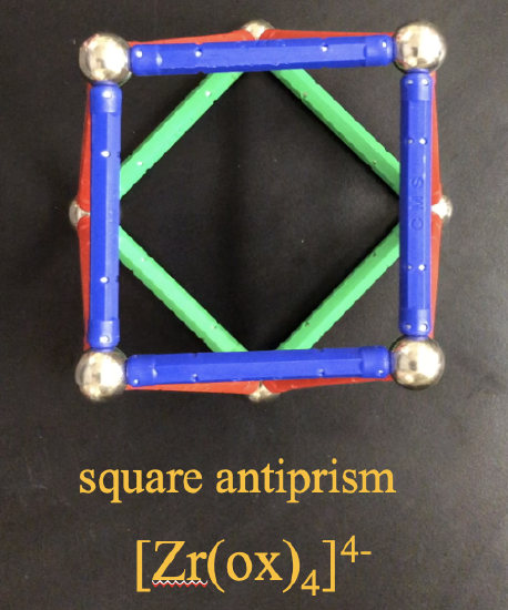
An example of a coordination compound that makes a square antiprism is the tetraoxolato zirconate(4-) anion.
A structure related to the square antiprism is the dodecahedron. Note that we are not talking about the dodecahedron that is a platonic solid here. We can derive the dodecahedron by squeezing on the two opposite corners of the two squares. This distorts and bends a square to form two additional triangular faces. This produces the dodecahedron (Fig. 5.3.26).
A video of the square antiprism to dodecahedron transformation can be accessed through the link below:
https://www.youtube.com/watch?v=A8G7...ature=youtu.be
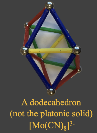
An example for this shape is the complex octacyanomolybdate (3-), (Fig. 5.3.26). As you can see from the examples, all metal ions are large metal ions, and the ligands a small, confirming that structures with large coordination numbers are favored by large metal ions and small ligands.
CN = 9
Finally, let us think about shapes associated with the coordination number 9.
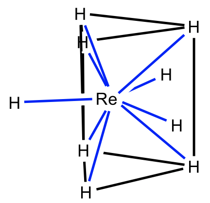
One possible shape is the tricapped trigonal prism for which the nonahydridorhenate is an example (Fig. 5.3.27). Here three additional ligands are placed above the three rectangular faces of the trigonal prism. Unsurprisingly, the ligands are small, and the metal ion is large.
Another example is the tricapped antiprism. The nonaammine lanthanum(3+) cation is an example. In this case the three additional ligands are placed above three triangular faces of an antiprism. The coordination number 9 is not the upper limit for coordination numbers. Coordination numbers up to 16 have been observed, but they are rare.
Dr. Kai Landskron (Lehigh University). If you like this textbook, please consider to make a donation to support the author's research at Lehigh University: Click Here to Donate.


