
4. Connecting the UV-visible Absorbance Detector to the National Instruments Breakout Box
- Page ID
- 62443

\( \newcommand{\vecs}[1]{\overset { \scriptstyle \rightharpoonup} {\mathbf{#1}} } \) \( \newcommand{\vecd}[1]{\overset{-\!-\!\rightharpoonup}{\vphantom{a}\smash {#1}}} \)\(\newcommand{\id}{\mathrm{id}}\) \( \newcommand{\Span}{\mathrm{span}}\) \( \newcommand{\kernel}{\mathrm{null}\,}\) \( \newcommand{\range}{\mathrm{range}\,}\) \( \newcommand{\RealPart}{\mathrm{Re}}\) \( \newcommand{\ImaginaryPart}{\mathrm{Im}}\) \( \newcommand{\Argument}{\mathrm{Arg}}\) \( \newcommand{\norm}[1]{\| #1 \|}\) \( \newcommand{\inner}[2]{\langle #1, #2 \rangle}\) \( \newcommand{\Span}{\mathrm{span}}\) \(\newcommand{\id}{\mathrm{id}}\) \( \newcommand{\Span}{\mathrm{span}}\) \( \newcommand{\kernel}{\mathrm{null}\,}\) \( \newcommand{\range}{\mathrm{range}\,}\) \( \newcommand{\RealPart}{\mathrm{Re}}\) \( \newcommand{\ImaginaryPart}{\mathrm{Im}}\) \( \newcommand{\Argument}{\mathrm{Arg}}\) \( \newcommand{\norm}[1]{\| #1 \|}\) \( \newcommand{\inner}[2]{\langle #1, #2 \rangle}\) \( \newcommand{\Span}{\mathrm{span}}\)\(\newcommand{\AA}{\unicode[.8,0]{x212B}}\)
These instructions are specific for the UV-visible absorbance detector and National Instruments breakout box in the parts lists. If you are using different equipment, ignore the instructions in this section. Follow the manufacturer’s instructions specific to the instrument you are using.
- Cut and strip the ends of two 18” lengths of 24 gauge electrical wire (red and black). Bend the exposed wire tip of the red wire into a loop and hook it around + terminal post. Tighten the screw while making sure the wire loop remains between the instrument panel and screw head. Repeat for the black wire, looping the wire tip and the – terminal post.
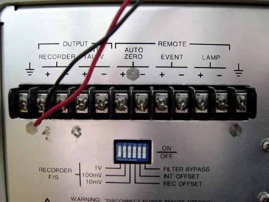
Detector (Back View Close-up)
- Open the breakout box. Loosen the screws holding the top plate of the retaining bracket located at the mouth of the box.
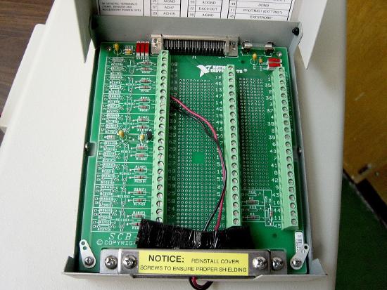
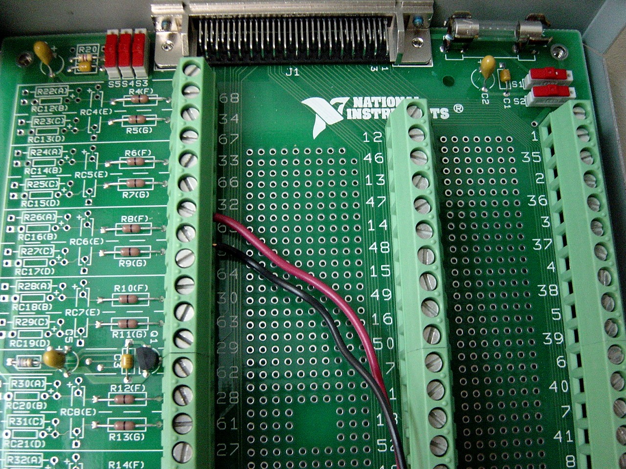
Breakout Box
- Pass the red and black electrical wires between the top and bottom plates of the retaining bracket.
- Loosen the screws for positions 65 and 31 in the upper left corner of the breakout box. Insert the exposed tip of the red wire into position 65 and the black wire into position 31. Retighten the screws, securing the wires into the terminals.
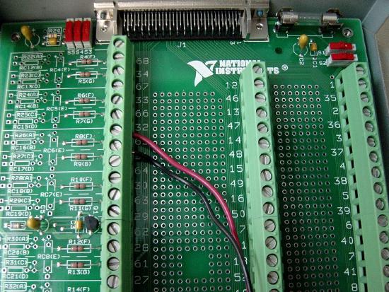
Breakout Box (Closeup)
- Tighten the screws on the retaining bracket so that the red and black electrical wires are held firmly in place. Close the breakout box and position on top of the UV-visible detector.
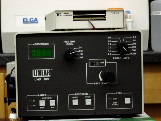
Breakout Box and Detector
- Cut two 18” lengths of shielded electrical wire (24 gauge). Using wire cutters, strip approximately ½” of the wire coating from each end of the two lengths.
- On the back of the UV-visible absorbance detector, loosen the screws for the + and – terminal of the recording output.
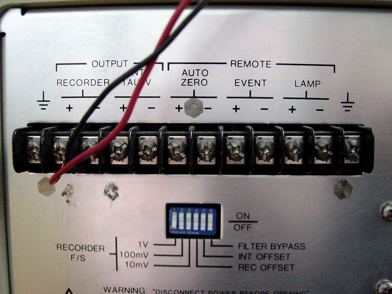


Detector (Back View)