
Ladder Networks
- Page ID
- 60129

Anyone who has turned on a light switch has run a one bit digital to analog converter (DAC). When the switch is off, output is zero. When it's on, the full potential of the power system (battery or power grid) is applied to whatever is beyond the switch. With a multibit DAC, we throw switches, and some fraction of a reference potential or current is transmitted to the device output.
There are two common networks used in DACs: resistive ladders and capacitive ladders. We will deal mainly with the former; the latter are used mostly in high speed DACs whose low frequency performance isn't particularly important (an example would be a DAC in an audio device. People can't hear ultra-low frequencies, so an offset in the DC or low-frequency performance is irrelevant).
How can we understand ladders? A step at a time. In all cases, we'll have some reference voltage Vref that is the full scale range of the DAC. For purposes of this section, presume that the DAC encodes straight binary from 0 to Vref. Other coding schemes aren't hard to understand once this first one is clear.
The first circuit to consider is a simple voltage divider. For two equal resistors, we have 3 points we can monitor: zero, the mid-point of the resistive ladder (where V = Vin/2), and the top of the ladder (where V = Vin). If we had an electronic switch, we could choose among 3 outputs. Clearly, given N resistors, we can select among N+1 outputs.

Unfortunately, there are problems with this simple design. Leaving out details of electrical engineering, we need N-1 resistors to get N output. If we want 12 bits of resolution, 212 = 4096, and that's a lot of resistors. Isn't there a way to use fewer resistors? It turns out that there's a method that uses only 2N resistors. It's called an R/2R ladder.
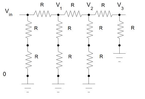
A 3-level R/2R Network
Start at the far right. How does V3 compare to V2? By analogy to the previous figure, V3 = V2/2. At first, it looks like computing how V2 and V1 relate could be ugly. However, there are 2 routes to ground from V2. Both of them have a total resistance of 2R. The effective resistance of two resistors in parallel relate as 1/Reffective = 1/Rpath 1 + 1/Rpath 2. The effective resistance from V2 to ground via the two parallel paths is R, the same as the resistance of the individual resistors! This means that each numbered voltage is 1/2 the potential of the next lower numbered voltage. Suddenly, we have a way to get 1/2n fractions of a reference potential for any n, just by using a large enough number of identical resistors. Actually, there's a limit; the precision of the resistors has to be such that the errors in each stage are smaller than the smallest fractional voltage. That means that, if we have a 12 bit ladder, all resistances must be precise to 1 part in 212 = 1/4096. That's about 0.025%. That sounds difficult to achieve, but resistors can be trimmed to 0.1% fairly easily, 0.01% with effort, and even 0.001% if temperature is carefully controlled and adequate standards are available.
We thus have a way to look at a reference potential and 1/2, 1/4, 1/8, ... of that reference. How do we combine those potentials so we can get potentials that vary in small, equal steps from 0 to Vin? We need to combine the current in the R/2R network with one amplifier. Let's take a moment to examine the Inverting Operational Amplifier With Gain, one of the most common analog electronic circuits.
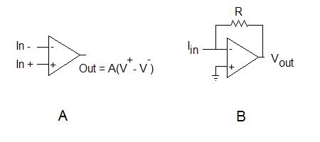
Inset A above is the symbol used for the collection of transistors that are, collectively, an operational amplifier. There are two inputs, + and -. The output voltage is equal to a gain A times the difference between the potentials of the two inputs. Typically, A is large, at least 104 and usually 106. Thus, a change of a few microvolts between the inputs can change the output by several volts. If we feed back some of the output to one of the inputs and anchor one input at a fixed potential, the only stable behavior is to have the potentials of the two inputs very close to each other. Thus, if we connect the output to the inverting (-) input, Vout = A(V+ - Vout) which, with a little algebra, gives Vout = A/(A+1) V+. Because A is big, A/(A+1) is close to 1, so the output potential equals the input. This re-enforces the point that the operational amplifier, properly wired, drives the potentials of its two inputs to nearly the same potential.
So now look at inset B. The inverting (-) input will be driven to ground potential. Because the inverting input is at ground potential but not physically wired to ground, it is said to be a "virtual ground." If the output is at a potential Vout, the current through the resistor R is just Vout/R. But where does that current come from? It all must come from the input current Iin since ideal operational amplifiers draw no current through their inputs. Thus, the current through R must be Iin. Using a consistent sign convention, if the input current comes from a positive voltage source, then passes the inverting input at V=0, the output must have a negative potential, so Vout = -Iin R.
We now combine the ladder network with the circuit in inset B. All but one of the grounds in the ladder network is connected via switches either to a real ground or to the virtual ground of the operational amplifier circuit. Here's a drawing.
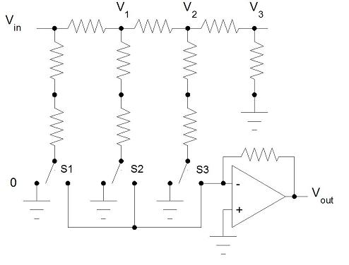
As far as the R/2R ladder is concerned, the operational amplifier circuit isn't even there. Either the points that were formerly grounded still are (the switches S1, S2, and S3 switched to the left) or they're connected to virtual ground (one or more of the switches switched to the right). Thus, the potentials we computed previously are unchanged. What happens to Vout as the switches are switched? Vout = -Iin R, but Iin comes from whichever branches of the resistive ladder are switched to the right.
If all of the switches are to the left, no current comes to the inverting input of the amplifier, and output = 0 V. What if only S3 is to the right? We already know that
V2 = Vin/4. This voltage drops across 2R to virtual common, so Iin = Vin/(4*2R) = Vin/(8R). So
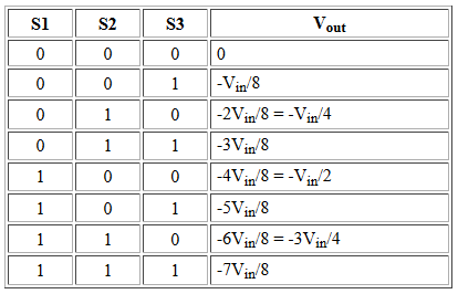
Vout = -Vin/8. Now fill in the following table. A "0" for a switch means it is connected to physical ground, while a "1" means it is connected to virtual common on the amplifier. Click here to pop up a window showing the full set of values.
| S1 | S2 | S3 | Vout |
|---|---|---|---|
| 0 | 0 | 0 | 0 |
| 0 | 0 | 1 | -Vin/8 |
| 0 | 1 | 0 | |
| 0 | 1 | 1 | |
| 1 | 0 | 0 | |
| 1 | 0 | 1 | |
| 1 | 1 | 0 | |
| 1 | 1 | 1 |
Voila! Straight binary coding of the switches gives a voltage proportional to that binary number! In fact, if (in this example) Vin=-8 V, then Vout is the binary number, expressed in volts.
It is now clear how a straight binary DAC works -- one simply uses an R/2R network and an appropriate reference potential.