
7.15: Matrix Mechanics Approach to Polarized Light - Version 2
- Page ID
- 140339

It is convenient and illustrative of quantum mechanical principles to use matrix mechanics to describe experiments with polarized light. In this tutorial we will restrict our attention to plane polarized light. However, it would be just as easy to use matrix mechanics to describe the behavior of circularly polarized light (see appendix).
In matrix mechanics we use vectors to represent states and matrices to represent measurement operator Light polarized in the vertical and horizontal directions will serve as base states and will be represented the following vectors. As will be shown shortly any other polarization state can be written as a linear superposition of these basis vectors.
\[ v = \begin{pmatrix} 1 \\ 0 \end{pmatrix} ~~~ h = \begin{pmatrix} 0 \\ 1 \end{pmatrix} \nonumber \]
\[ \begin{pmatrix} 1 & 0 \end{pmatrix} \begin{pmatrix} 1 \\ 0 \end{pmatrix} \rightarrow 1 ~~~ \begin{pmatrix} 0 & 1 \end{pmatrix} \begin{pmatrix} 0 \\ 1 \end{pmatrix} \rightarrow 1 ~~~ \begin{pmatrix} 1 & 0 \end{pmatrix} \begin{pmatrix} 0 \\ 1 \end{pmatrix} \rightarrow 0 \nonumber \]
\[ v^T v \rightarrow 1 ~~~ h^T h \rightarrow 1 ~~~ v^T h \rightarrow 0 \nonumber \]
Note from above that |v> and |h> form an orthonormal basis set for this two-dimensional vector space. Light polarized at an angle \( \theta\) relative to the verticle can be written as
\[ \Theta ( \theta) = \begin{pmatrix} \cos \theta \\ \sin \theta \end{pmatrix} \nonumber \]
It is easy to show that this state is normalized
\[ \begin{pmatrix} \cos \theta & \sin \theta \end{pmatrix} \begin{pmatrix} \cos \theta \\ \sin \theta \end{pmatrix} \rightarrow \cos \theta^2 + \sin \theta^2 simplify \rightarrow 1 \nonumber \]
In addition, \( | \theta \rangle\) can be written as a linear superposition of the polarization base states:
\[ | \theta \rangle = | v \rangle \langle v | \theta \rangle + | h \rangle \langle h | \theta \rangle = | v \rangle \cos \theta + | h \rangle \sin \theta \nonumber \]
\[ v \cos \theta + h \sin \theta \rightarrow \begin{pmatrix} \cos \theta \\ \sin \theta \end{pmatrix} \nonumber \]
A polarizing filter oriented in the vertical position in this basis can be represented by the following mat operator - |v><v|.
\( V_{op} = \begin{pmatrix} 1 \\ 0 \end{pmatrix} \begin{pmatrix} 1 & 0 \end{pmatrix} \rightarrow \begin{pmatrix} 1 & 0 \\ 0 & 0 \end{pmatrix}\) which can also be accomplished this way \( v v^T \rightarrow \begin{pmatrix} 1 & 0 \\ 0 & 0 \end{pmatrix}\)
Note the results of the following measurements on the three defined polarization states using this operator
\[ \begin{pmatrix} 1 & 0 \\ 0 & 0 \end{pmatrix} \begin{pmatrix} 1 \\ 0 \end{pmatrix} \rightarrow \begin{pmatrix} 1 \\ 0 \end{pmatrix} \nonumber \]
\[ \begin{pmatrix} 1 & 0 \\ 0 & 0 \end{pmatrix} \begin{pmatrix} 0 \\ 1 \end{pmatrix} \rightarrow \begin{pmatrix} 0 \\ 0 \end{pmatrix} \nonumber \]
\[ \begin{pmatrix} 1 & 0 \\ 0 & 0 \end{pmatrix} \begin{pmatrix} \cos \theta \\ \sin \theta \end{pmatrix} \rightarrow \begin{pmatrix} \cos \theta \\ 0 \end{pmatrix} \nonumber \]
\[ V_{op} v \rightarrow \begin{pmatrix} 1 \\ 0 \end{pmatrix} \nonumber \]
\[ V_{op} h \rightarrow \begin{pmatrix} 0 \\ 0 \end{pmatrix} \nonumber \]
\[ V_{op} \Theta ( \theta) \rightarrow \begin{pmatrix} \cos \theta \\ 0 \end{pmatrix} \nonumber \]
Vertically polarized light passes the vertical polarizer, horizontally polarized light is absorbed (anihilated and \( \theta\)-polarized light, if it passes, becomes vertically polarized with reduced intensity. The probability will pass the vertical polarizer is \( \cos^2 \theta\). The operators associated with a horizontal filter and a filter oriented at an angle \( \theta\) relative to the vertical shown below. The latter is, of course, general and can be used to represent any operator by putting in the appropriate value for \( \theta\) as is shown below.
\[ H_{op} = \begin{pmatrix} 0 \\ 1 \end{pmatrix} \begin{pmatrix} 0 & 1 \end{pmatrix} \rightarrow \begin{pmatrix} 0 & 0 \\ 0 & 1 \end{pmatrix} \nonumber \]
\[ \Theta_{op} ( \theta) = \begin{pmatrix} \cos \theta \\ \sin \theta \end{pmatrix} \begin{pmatrix} \cos \theta & \sin \theta \end{pmatrix} \rightarrow \begin{pmatrix} \cos \theta^2 & \cos \theta \sin \theta \\ \cos \theta \sin \theta & \sin \theta^2 \end{pmatrix} \nonumber \]
The operators for vertical, diagonal and horizontal polarizers are shown below using the general operator
\[ \Theta_{op} (0) \rightarrow \begin{pmatrix} 1 & 0 \\ 0 & 0 \end{pmatrix} \nonumber \]
\[ \Theta_{op} \left( \frac{ \pi}{4} \right) ~float,~1~ \rightarrow \begin{pmatrix} 0.5 & 0.5 \\ 0.5 & 0.5 \end{pmatrix} \nonumber \]
\[ \Theta_{op} \left( \frac{ \pi}{2} \right) \rightarrow \begin{pmatrix} 0 & 0 \\ 0 & 1 \end{pmatrix} \nonumber \]
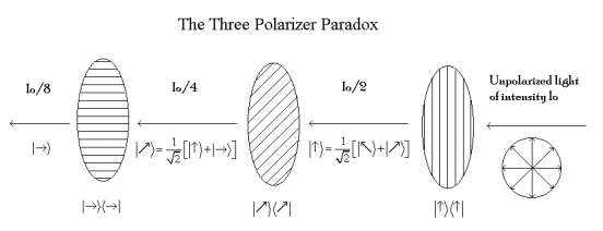
We now examine the three polarizer paradox illustrated in the figure below. Unpolarized light illuminates vertical polarizer and 50% of the light emerges as vertically polarized light. This light encounters a diagonal polarizer oriented at a 45o angle to the original vertical polarizer and 50% of it emerges as diagonally polarized light. Finally 50% of the diagonally polarized light passes a horizontally oriented polarizer. In other words 12.5% of the light illuminating the first vertical polarizer passes the final horizontal polarizer. However, if the diagonal polarizer sandwiched between the vertical and horizontal polarizers is remove no light emerges form the final horizontal polarizer.
Matrix mechanics will now be used to examine the so-called "three polarizer paradox." Please note that figure offers an alternative analysis based on Dirac bracket notation and the superposition principle.
Unpolarized light, such as that coming from an incandescent light bulb, might be considered to be an be mixture of all polarization angles between 0 and \( \frac{ \pi}{2}\) radians. The probability amplitude that a \( \theta\)-polarized photon will pass a vertical filter is
\[ \begin{pmatrix} 1 & 0 \end{pmatrix} \begin{pmatrix} 1 & 0 \\ 0 & 0 \end{pmatrix} \begin{pmatrix} \cos \theta \\ \sin \theta \end{pmatrix} \nonumber \]
The probability is the square of the absolute magnitude of the probability amplitude. Thus the fraction of a beam of unpolarized light that will pass a vertically oriented polarizer is 0.5. To achieve this result we must integrate over all possible polarization angles. The factor \(2/ \pi\) [(\( \pi\)/2)-1] normalizes the calculation.
\[ \frac{2}{ \pi} \int_{0}^{ \frac{ \pi}{2}} \left[ \begin{pmatrix} 1 & 0 \end{pmatrix} \begin{pmatrix} 1 & 0 \\ 0 & 0 \end{pmatrix} \begin{pmatrix} \cos \theta \\ \sin \theta \end{pmatrix} \right] ^2 d \theta = 0.5 \nonumber \]
\[ \frac{2}{ \pi} \int_{0}^{ \frac{ \pi}{2}} \left( v^T V_{op} \Theta ( \theta) \right) ^2 d \theta = 0.5 \nonumber \]
As is well known, and easy to demonstrate, the probability that unpolarized light (or light of any polarization) will pass two crossed polarizing films (vertical followed by horizontal for example) is 0.
\[ \frac{2}{ \pi} \int_{0}^{ \frac{ \pi}{2}} \left[ \begin{pmatrix} 0 & 1 \end{pmatrix} \begin{pmatrix} 0 & 0 \\ 0 & 1 \end{pmatrix} \begin{pmatrix} 1 & 0 \\ 0 & 0 \end{pmatrix} \begin{pmatrix} \cos \theta \\ \sin \theta \end{pmatrix} \right] ^2 d \theta = 0 \nonumber \]
\[ \frac{2}{ \pi} \int_{0}^{ \frac{ \pi}{2}} \left( v^T H_{op} V_{op} \Theta ( \theta) \right) ^2 d \theta = 0.5 \nonumber \]
However, if a polarizing film oriented diagonally at a 45o angle is inserted between the crossed polarizers light gets through the final horizontal filter. The operator for a 45o polarizer is obtained from \( \Theta_{op}\).
\[ \Theta_{op} \frac{ \pi}{4} = \begin{pmatrix} 0.5 & 0.5 \\ 0.5 & 0.5 \end{pmatrix} \nonumber \]
The following calculation shows that 12.5% of the unpolarized light illuminating the initial vertical filter gets through this arrangement of polarizing films in agreement with the figure above and experience.
\[ \frac{2}{ \pi} \int_{0}^{ \frac{ \pi}{2}} \left[ \begin{pmatrix} 0 & 1 \end{pmatrix} \begin{pmatrix} 0 & 0 \\ 0 & 1 \end{pmatrix} \begin{pmatrix} 0.5 & 0.5 \\ 0.5 & 0.5 \end{pmatrix} \begin{pmatrix} 1 & 0 \\ 0 & 0 \end{pmatrix} \begin{pmatrix} \cos \theta \\ \sin \theta \end{pmatrix} \right] ^2 d \theta = 0.125 \nonumber \]
\[ \frac{2}{ \pi} \int_{0}^{ \frac{ \pi}{2}} \left( h^T \Theta_{op} \frac{ \pi}{2} \Theta_{op} \frac{ \pi}{4} \Theta_{op} (0) \Theta ( \theta) \right) ^2 d \theta \rightarrow \frac{1}{8} \nonumber \]
In addition, the non-commutivity rule can be demonstrated by switching the second and third filters. When this is done no photons emerge from the apparatus for obvious reasons; the first two filters are crossed.
\[ \frac{2}{ \pi} \int_{0}^{ \frac{ \pi}{2}} \left[ \begin{pmatrix} 0 & 1 \end{pmatrix} \begin{pmatrix} 0.5 & 0.5 \\ 0.5 & 0.5 \end{pmatrix} \begin{pmatrix} 0 & 0 \\ 0 & 1 \end{pmatrix} \begin{pmatrix} 1 & 0 \\ 0 & 0 \end{pmatrix} \begin{pmatrix} \cos \theta \\ \sin \theta \end{pmatrix} \right] ^2 d \theta = 0 \nonumber \]
\[ \frac{2}{ \pi} \int_{0}^{ \frac{ \pi}{2}} \left( h^T \Theta_{op} \frac{ \pi}{4} \Theta_{op} \frac{ \pi}{2} \Theta_{op} (0) \Theta ( \theta) \right) ^2 d \theta \rightarrow 0 \nonumber \]
Appendix:
The base states for circularly polarized light are given below, along with their superpositions in the h-v representation.
\[ L = \frac{1}{ \sqrt{2}} \begin{pmatrix} 1 \\ i \end{pmatrix} ~~~ \frac{1}{ \sqrt{2}} (v + ih) = \begin{pmatrix} 0.707 \\ 0.707i \end{pmatrix} \nonumber \]
\[ R = \frac{1}{ \sqrt{2}} \begin{pmatrix} 1 \\ -i \end{pmatrix} ~~~ \frac{1}{ \sqrt{2}} (v - ih) = \begin{pmatrix} 0.707 \\ -0.707i \end{pmatrix} \nonumber \]
Left and right circularly polarized light also form an orthonormal basis set.
\[ \overline{L^T} L \rightarrow 1 \nonumber \]
\[ \overline{R^T} R \rightarrow 1 \nonumber \]
\[ \overline{L^T} R \rightarrow 0 \nonumber \]
\[ \overline{R^T} L \rightarrow 0 \nonumber \]
The appropriate operators are:
\[ L_{op} = L \overline{L^T} ~ float,~1 \rightarrow \begin{pmatrix} 0.5 & -0.5i \\ 0.5i & 0.5 \end{pmatrix} \nonumber \]
\[ R_{op} = R \overline{R^T} ~ float,~1 \rightarrow \begin{pmatrix} 0.5 & 0.5i \\ -0.5i & 0.5 \end{pmatrix} \nonumber \]
Vertically and horizontally polarized light can be written as superpositions of circularly polarized light
\[ v = \frac{1}{ \sqrt{2}} (L+R) \rightarrow \begin{pmatrix} 1 \\ 0 \end{pmatrix} \nonumber \]
\[ h = \frac{i}{ \sqrt{2}} (R-L) \rightarrow \begin{pmatrix} 0 \\ 1 \end{pmatrix} \nonumber \]
Earlier unpolarized light was considered to be an even mixture of all polarization angles between 0o and Another approach is to consider it to be a 50-50 mixture of any two orthogonal polarization angles. The expectation value for unpolarized light passing a vertical polarizer under this model is outlined below.
\[ \langle V \rangle = \sum_i p_i \left\langle \psi_i \right| \hat{V} \left| \psi_i \right\rangle = \frac{1}{2} \langle \Theta | \hat{V} | \Theta \rangle + \frac{1}{2} \left\langle \Theta + \frac{ \pi}{2} \right| \hat{V} \left| \Theta + \frac{ \pi}{2} \right\rangle = \frac{1}{2} \langle \Theta | v \rangle \langle v | \Theta \rangle + \frac{1}{2} \left\langle \Theta + \frac{ \pi}{2} | v \right\rangle \left\langle v | \Theta + \frac{ \pi}{2} \right\rangle \nonumber \]
Just as calculated earlier 50% of the unpolarized light passes the vertical polarizer.
\[ \frac{1}{2} \Theta ( \theta) ^T V_{op} \Theta ( \theta) + \frac{1}{2} \Theta \left( \theta + \frac{ \pi}{2} \right) V_{op} \Theta \left( \theta + \frac{ \pi}{2} \right) ~ simplify \rightarrow \frac{1}{2} \nonumber \]
Unpolarized light can also be represented by the density operator shown below.
\[ \hat{ \rho} = \frac{1}{2} \left| \Theta \right\rangle \left\langle \Theta \right| + \frac{1}{2} \left| \Theta + \frac{ \pi}{2} \right\rangle \left\langle \Theta + \frac{ \pi}{2} \right| \nonumber \]
\[ \rho = \frac{1}{2} \Theta_{op} ( \theta) + \frac{1}{2} \Theta_{op} \left( \theta + \frac{ \pi}{2} \right)~simplify~ \rightarrow \begin{pmatrix} \frac{1}{2} & 0 \\ 0 & \frac{1}{2} \end{pmatrix} \nonumber \]
It is not difficult to show that the expectation value for unpolarized light passing a verticle polarizer can be calculated as the trace of the product of this operator with the vertical polarization operator.
\[ Tr \left[ \left( \frac{1}{2} \left| \theta \right\rangle \langle \Theta \left| \Theta + \frac{ \pi}{2} \right\rangle \left\langle \Theta + \frac{ \pi}{2} \right| \right) \hat{V} \right] = \frac{1}{2} \nonumber \]
\[ tr( \rho V_{op}) ~simplify~ \rightarrow \frac{1}{2} \nonumber \]
Of course there is nothing special about the vertical direction. Unpolarized light has a 50% probability passing a polarizer of any other orientation.
\[ tr( \rho H_{op}) = 0.5 \nonumber \]
\[ tr( \rho L_{op}) = 0.5 \nonumber \]
\[ tr( \rho R_{op}) = 0.5 \nonumber \]
\[ tr \left( \rho \Theta _{op} \left( \frac{ \pi}{3} \right) \right) = 0.5 \nonumber \]
\[ tr \left( \rho \Theta _{op} \left( \frac{ \pi}{4} \right) \right) = 0.5 \nonumber \]
\[ tr \left( \rho \Theta _{op} \left( \frac{ \pi}{8} \right) \right) = 0.5 \nonumber \]
In other words, the intensity of light passing a polarizer from an unpolarized source is independent of t orientation of the polarizer. Finally, the result of the three-polarizer demonstration is recalculated using the density matrix approach.
\[ D_{op} = \Theta \left( \frac{ \pi}{4} \right) \nonumber \]
\[ tr(H_{op} D_{op}) tr(D_{op} V_{op}) tr( V_{op} \rho) \rightarrow \frac{1}{8} \nonumber \]