1.40: Another look at the Consequences of Path Information in a Mach-Zehnder Interferometer
- Page ID
- 144054

This tutorial deals with the effect of path information and its so-called erasure in a Mach-Zehnder interferometer (MZI). A related analysis involving the double-slit experiment is available with the title "Which Path Information and the Quantum Eraser."
The source emits vertically polarized photons in the x-direction illuminating a 50/50 beam splitter (BS) which splits the beam into a superposition of propagation in the x- and y-directions. The reflected beam collects a 90 degree (\(\frac{\pi}{2}\),i) phase shift relative to the transmitted beam. A polarization rotator rotates the polarization in the lower arm to horizontal. Mirrors redirect the two beams to a second 50/50 BS. In the absense of the polarization rotator the photons are always registered at Dx and never at Dy. In its presence the detectors both fire 50% of the time. The algebraic analyses below the figure show the evolution of the photons through the interferometer in the absence and presence of the polarization rotator. Note that the orthogonal v/h polarization tags have become orthogonal d/a tags. The significance of this will be come clear in the matrix mechanics analysis that is provided below.
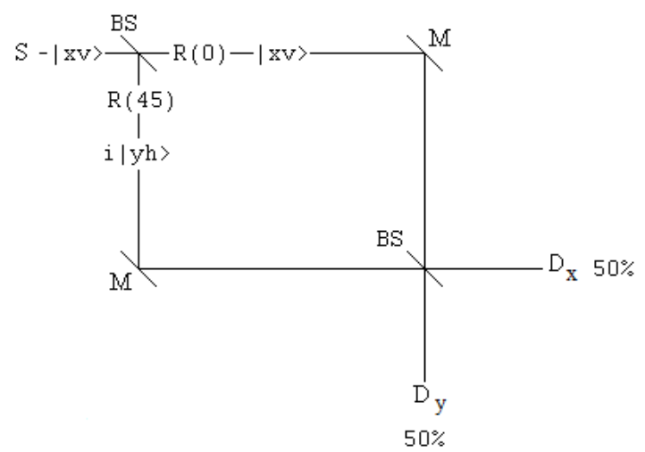
Photon behavior in the absence of the polarization rotator in the lower arm of the interferometer.
\[
| x v \rangle \stackrel{B S}{\longrightarrow}\frac{1}{\sqrt{2}}( | x v\rangle+ i | y v \rangle ) \stackrel{B S}{\longrightarrow}\frac{1}{2}(i | x v\rangle+| y v \rangle+i | x v \rangle-| y v \rangle )=i | x v \rangle
\nonumber \]
Photon behavior in the presence of the polarization rotator in the lower arm of the interferometer.
\[
| x v \rangle \stackrel{B S}{\longrightarrow} \frac{1}{\sqrt{2}}( | x v\rangle+ i | y v \rangle ) \xrightarrow[M]{y/h} \frac{1}{\sqrt{2}}( | y v\rangle+ i | x h \rangle ) \stackrel{B S}{\longrightarrow} \frac{1}{2}(i | x v\rangle+| y v \rangle+i | x h \rangle-| y h \rangle )=\frac{1}{\sqrt{2}}(i | x d\rangle+| y a \rangle )
\nonumber \]
The following equations were used to reach the final state:
\[
| d \rangle=\frac{1}{\sqrt{2}}( | h\rangle+| v \rangle ) \qquad | a \rangle=\frac{1}{\sqrt{2}}( | h\rangle-| v \rangle )
\nonumber \]
A matrix mechanics analysis uses vectors to represent states and matrices to represent the optical elements that they encounter in the MZI.
| Photon moving horizontally: \(\mathrm{x} :=\left( \begin{array}{l}{1} \\ {0}\end{array}\right)\) | Photon moving vertically: \(\mathrm{y} :=\left( \begin{array}{l}{0} \\ {1}\end{array}\right)\) | Vertical polarization: \(\mathrm{v} :=\left( \begin{array}{l}{1} \\ {0}\end{array}\right)\) | Horizontal polarization: \(\mathrm{h}=\left( \begin{array}{l}{0} \\ {1}\end{array}\right)\) |
Photon direction of propagation and polarization states:
\[
\mathrm{xv} :=\left( \begin{array}{c}{1} \\ {0} \\ {0} \\ {0}\end{array}\right) \quad \mathrm{xh} :=\left( \begin{array}{l}{0} \\ {1} \\ {0} \\ {0}\end{array}\right) \quad \mathrm{yv} :=\left( \begin{array}{c}{0} \\ {0} \\ {1} \\ {0}\end{array}\right) \quad \mathrm{yh} :=\left( \begin{array}{l}{0} \\ {0} \\ {0} \\ {1}\end{array}\right)
\nonumber \]
Projection operators for the x- and y-detectors:
\[
\mathrm{D} \mathrm{x} :=\mathrm{x} \cdot \mathrm{x}^{\mathrm{T}}=\left( \begin{array}{cc}{1} & {0} \\ {0} & {0}\end{array}\right) \qquad \mathrm{Dy} :=\mathrm{y} \cdot \mathrm{y}^{\mathrm{T}}=\left( \begin{array}{ll}{0} & {0} \\ {0} & {1}\end{array}\right)
\nonumber \]
Beam splitter:
\[
\mathrm{BS} :=\frac{1}{\sqrt{2}} \left( \begin{array}{ll}{1} & {\mathrm{i}} \\ {\mathrm{i}} & {1}\end{array}\right)
\nonumber \]
Mirror:
\[
M :=\left( \begin{array}{ll}{0} & {1} \\ {1} & {0}\end{array}\right)
\nonumber \]
Identity:
\[
\mathrm{I} :=\left( \begin{array}{ll}{1} & {0} \\ {0} & {1}\end{array}\right)
\nonumber \]
Polarization rotator for the lower arm of the interferometer:
\[
\mathrm{R}(\varphi) :=\left( \begin{array}{cccc}{1} & {0} & {0} & {0} \\ {0} & {-1} & {0} & {0} \\ {0} & {0} & {\cos (2 \cdot \varphi)} & {\sin (2 \cdot \varphi)} \\ {0} & {0} & {\sin (2 \cdot \varphi)} & {-\cos (2 \cdot \varphi)}\end{array}\right)
\nonumber \]
Diagonal and anti-diagonal projection operators:
\[
\operatorname{Pd} :=\frac{1}{2} \cdot \left( \begin{array}{cccc}{1} & {1} & {0} & {0} \\ {1} & {1} & {0} & {0} \\ {0} & {0} & {1} & {1} \\ {0} & {0} & {1} & {1}\end{array}\right)
\nonumber \]
\[
\mathrm{Pa} :=\frac{1}{2} \cdot \left( \begin{array}{cccc}{1} & {-1} & {0} & {0} \\ {-1} & {1} & {0} & {0} \\ {0} & {0} & {1} & {-1} \\ {0} & {0} & {-1} & {1}\end{array}\right)
\nonumber \]
Vertical and horizontal projection operators:
\[
\mathrm{Pv} :=\left( \begin{array}{cccc}{1} & {0} & {0} & {0} \\ {0} & {0} & {0} & {0} \\ {0} & {0} & {1} & {0} \\ {0} & {0} & {0} & {0}\end{array}\right)
\nonumber \]
\[
\mathrm{Ph} :=\left( \begin{array}{llll}{0} & {0} & {0} & {0} \\ {0} & {1} & {0} & {0} \\ {0} & {0} & {0} & {0} \\ {0} & {0} & {0} & {1}\end{array}\right)
\nonumber \]
MZI with lower arm polarization rotator:
\[\mathrm{MZ} (\varphi) : = \text{kronecker} (\text{BS, I}) \cdot \mathrm{R} (\varphi) \cdot \text{kronecker} (\text{M, I}) \cdot \text{kronecker} (\text{BS, I}) \nonumber \]
Without polarization rotation in the lower arm of the interferometer all photons are detected at Dx. See the algebraic analysis.
\[
(|\mathrm{kronecker}(\mathrm{Dx}, \mathrm{I}) \cdot \mathrm{MZ}(0) \cdot \mathrm{xv}|)^{2}=1 \qquad (|\mathrm{kronecker}(\mathrm{Dy}, \mathrm{I}) \cdot \mathrm{MZ}(0) \cdot \mathrm{xv}|)^{2}=0
\nonumber \]
Adding orthogonal path information by rotating the polarization in the lower arm to horizontal destroys the interference effect at the second beam splitter causing both detectors to register photons. See the algebraic analysis.
\[
\left(|\mathrm{kronecker}(\mathrm{Dx}, \mathrm{I}) \cdot \mathrm{M} Z\left(\frac{\pi}{4}\right) \cdot \mathrm{xv}|\right)^{2}=0.5 \qquad \left( | \text { kronecker }(\mathrm{Dy}, \mathrm{I}) \cdot \mathrm{MZ}\left(\frac{\pi}{4}\right) \cdot \mathrm{xv} |\right)^{2}=0.5
\nonumber \]
Placing vertical or horizontal polarizers in front of both detectors reduces the count rates by half. See the algebraic analysis.
\[
\left(|\mathrm{kronecker}(\mathrm{Dx}, \mathrm{I}) \cdot \mathrm{Pv} \cdot \mathrm{MZ}\left(\frac{\pi}{4}\right) \cdot \mathrm{xv}|\right)^{2}=0.25 \qquad \left(|\mathrm{kronecker}(\mathrm{Dy}, \mathrm{I}) \cdot \mathrm{Pv} \cdot \mathrm{MZ}\left(\frac{\pi}{4}\right) \cdot \mathrm{xv}|\right)^{2}=0.25
\nonumber \]
\[
\left(|\mathrm{kronecker}(\mathrm{Dx}, \mathrm{I}) \cdot \mathrm{Ph} \cdot \mathrm{M} \mathrm{Z}\left(\frac{\pi}{4}\right) \cdot \mathrm{xv}|\right)^{2}=0.25 \qquad \left( | \text { kronecker }(\mathrm{Dy}, \mathrm{I}) \cdot \mathrm{Ph} \cdot \mathrm{MZ}\left(\frac{\pi}{4}\right) \cdot \mathrm{xv} |\right)^{2}=0.25
\nonumber \]
A diagonal polarizer placed in front of both detectors passes the x-direction photons and absorbs the y-direction photons. See the algebraic analysis.
\[
\left(|\mathrm{kronecker}(\mathrm{Dx}, \mathrm{I}) \cdot \mathrm{Pd} \cdot \mathrm{MZ}\left(\frac{\pi}{4}\right) \cdot \mathrm{xv}|\right)^{2}=0.5 \qquad \left(|\mathrm{kronecker}(\mathrm{Dy}, \mathrm{I}) \cdot \mathrm{Pd} \cdot \mathrm{MZ}\left(\frac{\pi}{4}\right) \cdot \mathrm{xv}|\right)^{2}=0
\nonumber \]
An anti-diagonal polarizer placed in front of the detectors passes the y-direction photons and absorbs the x-direction photons. See the algebraic analysis.
\[
\left( | \text { kronecker }(\mathrm{D} \mathrm{x}, \mathrm{I}) \cdot \mathrm{Pa} \cdot \mathrm{MZ}\left(\frac{\pi}{4}\right) \cdot \mathrm{xv} |\right)^{2}=0 \qquad \left( | \text { kronecker }(\mathrm{Dy}, \mathrm{I}) \cdot \mathrm{Pa} \cdot \mathrm{MZ}\left(\frac{\pi}{4}\right) \cdot \mathrm{xv} |\right)^{2}=0.5
\nonumber \]
These calculations demonstrate that the lower arm polarization rotator does its job.
\[
\mathrm{R}(0) \cdot \mathrm{kronecker}(\mathrm{BS}, \mathrm{I}) \cdot \mathrm{xv}=\left( \begin{array}{c}{0.707} \\ {0} \\ {0.707 \mathrm{i}} \\ {0}\end{array}\right) \frac{\mathrm{xv}+\mathrm{i} \cdot \mathrm{yv}}{\sqrt{2}}=\left( \begin{array}{c}{0.707} \\ {0} \\ {0.707 \mathrm{i}} \\ {0}\end{array}\right)
\nonumber \]
\[
\mathrm{R}\left(\frac{\pi}{4}\right) \cdot \mathrm{kronecker}(\mathrm{BS}, \mathrm{I}) \cdot \mathrm{xv}=\left( \begin{array}{c}{0.707} \\ {0} \\ {0} \\ {0.707 \mathrm{i}}\end{array}\right) \frac{\mathrm{xv}+\mathrm{i} \cdot \mathrm{yh}}{\sqrt{2}}=\left( \begin{array}{c}{0.707} \\ {0} \\ {0} \\ {0.707 \mathrm{i}}\end{array}\right)
\nonumber \]
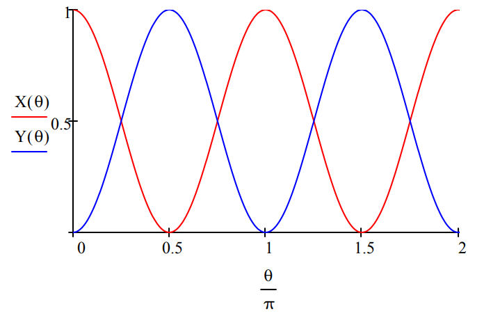
The following calculations show the behavior of the detectors as a function of the polarization rotator angle.
Detection at Dx:
\[
\mathrm{X}(\theta) :=(|\mathrm{kronecker}(\mathrm{Dx}, \mathrm{I}) \cdot \mathrm{MZ}(\theta) \cdot \mathrm{xv}|)^{2}
\nonumber \]
Detection at Dy:
\[
\mathrm{Y}(\theta) :=(|\mathrm{kronecker}(\mathrm{Dy}, \mathrm{I}) \cdot \mathrm{MZ}(\theta) \cdot \mathrm{xv}|)^{2}
\nonumber \]