
20.6F: The d² Configuration
- Page ID
- 34399
We have already looked at Transition metal ion complexes with D ground states which accounts for the d1, d4, d6 and d9 configurations.
We turn now to d2, d3, d7 and d8 configurations for which the ground state of the free ions are given by Russell-Saunders F terms.
In octahedral and tetrahedral crystal fields, the F state is split into A2(g), T1(g) and T2(g) terms, while the P term generates an additional T1(g) term. Once again we can make use of the analogy to the splitting of orbitals in a crystal field so in this case we can look at how the f-orbitals lose their 7-fold degeneracy in an octahedral field.
It should be noted that whenever the ground state is an F term there will be a P term found at higher energy with the same spin multiplicity. The separation of these terms in the free ion is measured in terms of the B Racah parameter and is equivalent to 15B (where B is usually around 1000 cm-1).
Once again, one approach taken to aid in the interpretation of these spectra is to use an Orgel diagram. The relevant Orgel diagram for the F ground state is given below:
oct d3,d8 tet d2,d7 ←-----------------------------------→ oct d2,d7 tet d3,d8
| ν1 = Δ (T2g←A2g) | ν1= 4/5 Δ + x (T2g←T1g) |
| ν2 = 9/5 Δ - x (T1g←A2g) | ν2 = 9/5 Δ + x (A2g←T1g) OR ν2 = 3/5 Δ + 15B + 2x (T1g(P)←T1g) |
| ν3 = 6/5 Δ + 15B + x (T1g(P)←A2g) | ν3 = 3/5 Δ + 15B + 2x (T1g(P)←T1g) OR ν3 = 9/5 Δ + x (A2g←T1g) |
The lines showing the A2 and T2 terms are linear and depend solely on Δ. The "non-crossing rule" results in the lines for the two T1 terms being curved to avoid each other and as a result this introduces a "configuration interaction" in the transition energy equations.
That is, whenever there are lines with equivalent Russell-Saunders terms on the Orgel diagram they are not allowed to cross and are found to diverge. All other lines are expected to be linear.
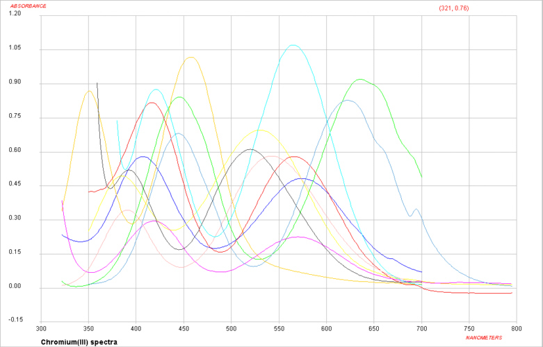
Visible spectra of some Cr(III) complexes
For Cr(III) complexes, we would start by writing the free ion electronic configuration as d3 and in an octahedral crystal field this would be described as t2g3 eg0.
The Russell-Saunders scheme that takes into account the electron-electron interactions would be described by a free ion ground state of 4F. To decide which side of the F Orgel diagram should be applied to the interpretation can be quickly determined by looking at the electronic configuration and noting that the ground state is singly degenerate (i.e. we need the left-hand-side where the lowest term is A2).
It is expected then that there should be 3 absorption bands found in the electronic spectrum. The energy of the first transition corresponds directly to Δ and the transition is written as 4T2g ← 4A2g.
If we now consider the d2 electronic configuration, then the Russell-Saunders free ion ground term state is a 3F. For an octahedral complex, the lowest energy state is a triplet which tells us that we need to be using the right-hand-side of the F Orgel diagram.
The first transition is written as 3T2g ← 3T1g and the energy of this transition does NOT correspond directly to Δ. It should be carefully noted that when using this side of the F-Orgel diagram none of the expected transitions correspond exactly to Δ . Interpretation of d2 spectra are made even more complicated since as we increase the size of Δ we note that at some point the 3T1g(P) and 3A2g lines cross. To determine the sequence of the transitions (that is whether we are on the left-hand-side or right-hand-side of the intersection) normally requires that all 3 absorption bands can be observed. This is often not the case and an alternative approach to interpretation of these spectra is needed. One such approach makes use of what are known as Tanabe-Sugano diagrams.