
4.2: Calcium the Archetypal Alkaline Earth Metal
- Page ID
- 212631

Calcium represents the typical Group 2 metal. The chemical properties of its compounds can be applied to all the heavier homologs.
Solid state
In the solid state the compounds of the alkaline metals generally form ionic lattices. In fact (except for beryllium and to a lesser extend magnesium) the lattice parameters calculated from the ionic radii of Group 2 metals are within 1% of the experimentally determined values, indicating the highly ionic character.
Due to the increased ionic charge the cations of the alkaline earths are less than that of their alkali metal neighbors. Thus, the ionic radius of Ca2+ (0.99 Å) is less than that of K+ (1.33 Å), but more similar to Na+ (0.97 Å). This diagonal relationship is seen for the other metals in Group 2.
Oxides
Combustion of the Group 2 metals gives the monoxide, MO. In the case of SrO and BaO further reaction occurs by the absorption of oxygen under pressure to give the peroxides, MO2. The peroxide and superoxides are not stable for the lighter homologs because the smaller M2+ ions are more polarizing and cause the peroxide and superoxides to decompose to the monoxide. Calcium peroxide can be prepared by the reaction of the hydroxide with hydrogen peroxide.
\[ Ca(OH)_2 + H_2O_2 + 6 H_2O \rightarrow CaO_2 \cdot 8 H_2O\]
As typical for the Group 2 oxides, calcium monoxide is basic and reacts with water to give the hydroxide, (4.2.2). In fact, thin films of the Group 2 oxides of calcium, barium and strontium will readily absorb water and form the hydroxides.
\[ CaO + H_2O \rightarrow Ca(OH)_2 \]
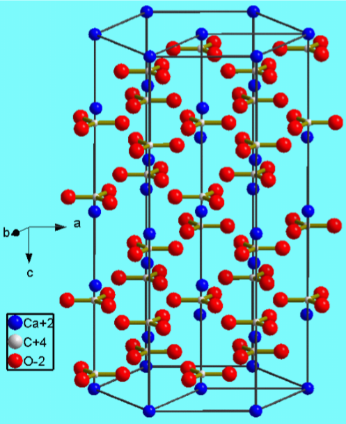
Carbonate
Calcium carbonate (CaCO3) is a common substance found in rock in all parts of the world, and is the main component of shells of marine organisms, snails, pearls, and eggshells. Calcium carbonate is usually the principal cause of hard water. Most calcium carbonate used is extracted by quarrying or mining. However, pure calcium carbonate (e.g., for pharmaceutical use) can be produced from a pure quarried source (usually marble) or manufactured by the sequential reaction involving the thermal decomposition of the carbonate to the monoxide, (4.2.3), followed by the reaction with water to give the hydroxide, (4.2.2), and finally, the reaction with carbon dioxide to reform the carbonate, (4.2.4).
\[ CaCO_3 \rightarrow CaO + CO_2 \]
\[ Ca(OH)_2 + CO_2 \rightarrow CaCO_3 + H_2O \]
Calcium carbonate crystallizes as a variety of mineral forms.
- Aragonite
- Calcite (Figure \(\PageIndex{4}\).13)
- Vaterite
- Chalk
- Travertine
- Limestone
- Marble
Calcium carbonate is one of the most widely used mineral materials, the following represents a list of some of the main applications.
- Construction industry as a building material (marble) or as an ingredient of cement.
- Purification of iron from iron ore in a blast furnace.
- A drilling fluids in the oil industry.
- Filler material for latex gloves.
- Filler (extender) in paints.
- Filler in plastics.
- Babies' diapers.
- DIY adhesives, sealants, and decorating fillers.
- Whiting in ceramics/glazing application.
- The filler in glossy paper.
- The production of blackboard chalk (CaSO4).
- An abrasive in household cleaning products.
- Dietary calcium supplement.
- Inert filler for tablets and pharmaceuticals.
- Toothpaste.
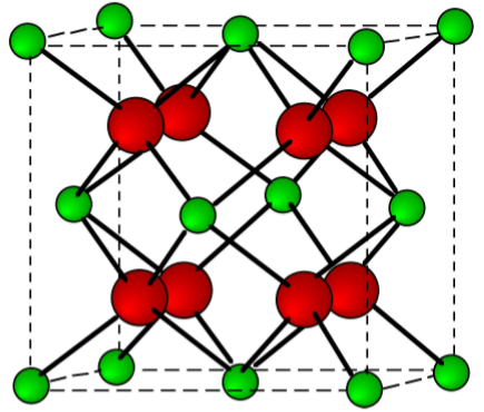
Halides
Calcium chloride, bromide, and iodide are all ionic, water-soluble salts. In contrast, due to its high lattice energy for the small fluoride ion, CaF2 is only slightly soluble (Table \(\PageIndex{4}\).5). The fluorite structure typified for CaF2 (Figure \(\PageIndex{4}\).14) is found for most of the MX2 ionic solids.
| Compound | Solubility @ 20 °C (g/100 mL) | Solubility @ 100 °C (g/100 ml) |
|---|---|---|
| CaF2 | 0.0016 | 0.0017 |
| CaCl2 | 74.5 | 159 |
| CaBr2 | 142 | 312 |
| CaI2 | 209 | 426 |
Complexes
The coordination complexes of the alkaline earth metal cations (M2+) involve electrostatic, or ion-dipole, interactions that have no preferred direction of interaction. Calcium will tolerate a wide range of coordination numbers, however, 6 and 8 are the most common. Complexes generally form with oxygen donors in a wide range of ligands, including: ROH, R2O, R2C=O, RCO2-, and PO42-. While complexes with nitrogen donor ligands are known they are usually present with oxygen donors as well. As with the Group 1 metals, the aquo complex readily exchanges the water for other ligands, however, since the bond energy is larger for Ca2+ than for Na+, the equilibrium constants are larger for analogous complexes.
Bibliography
- J. M. Buriak, L. K. Cheatham, R. G. Gordon, J. J. Graham, and A. R. Barron, Euro J. Solid State Inorg. Chem., 1992, 29, 43.
- R. E. Anderson and A. R. Barron, Main Group Chem., 2005, 4, 279.
- C, Lupu, R. S. Arvidson, A. Lüttge and A. R. Barron, Chem. Commun., 2005, 2354.
Calcium Carbide: From Gaslight to Fertilizer
Calcium carbide has an interesting role in the societal and commercial changes that took place in the late 19th and early 20th centuries. However, in order to understand the effects of calcium carbide it is important to realize the state of the art of lighting in the late 18th century.
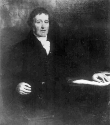
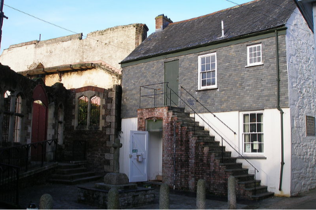
It was in 1792 that William Murdoch (Figure \(\PageIndex{4}\).15) first began experimenting with the use of gas, derived from the heating of coal and other materials, for lighting. Murdoch produced this coal gas, or manufactured gas and conveyed it through metal pipes, lighting his cottage and offices in Redruth, Cornwall (Figure \(\PageIndex{4}\).16).
In 1802 as part of the public celebrations of the Peace of Amiens (between England and France) Murdoch made a public exhibition of his lighting by illuminating the exterior of the Soho Foundry in Birmingham, England. Then in 1807 an entrepreneur, Fredrick Winsor (originally Friedrich Albrecht Winzer) displayed gaslights along the top of the wall between Carlton House and the Mall in London. This demonstration for city use was a revelation. By 1823 Britain had 300 miles of gas pipe and by 1850 it was 2000 miles. Gaslight had a profound impact on society. Walking the streets at night was safer, and it allowed for longer working hours. It also made evening activities easier. As a consequence reading and evening schools became popular pastimes. Unfortunately, gaslight was rather dull orange in color (Figure \(\PageIndex{4}\).17), but it was due to another area of chemical research that a brighter alternative was discovered.

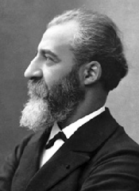
In 1895 the Frenchman Henry Moissan (Figure \(\PageIndex{4}\).18) was trying to make diamonds by the reaction of carbon (graphite) with almost anything he could lay his hands on. Although highly unsuccessful, one of his experiments did prove useful. By reacting carbon with lime, the common name for calcium oxide (CaO) at 2000 ◦C (in an electric arc furnace that he had helped develop) he produced calcium carbide (CaC2).
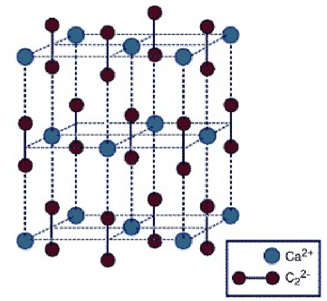
Pure calcium carbide is colorless, but most samples have a color ranging from black to grayish-white, depending on the grade. As an ionic salt it has a high melting point (2160 ◦C). While the structure of calcium carbide (Figure \(\PageIndex{4}\).19) has a tetragonal lattice, it is related to that of a cubic rock salt structure, but where the anion is the linear C22- moiety.
Although now used extensively, at the time of its discovery calcium carbide itself did not prove very interesting, its reaction with water had a profound effect on illumination. The reaction of calcium carbide with water yields acetylene, (4.2.5).
\[ \text{Ca}_2\text{C} + \text{H}_2\text{O} \rightarrow \text{Ca(OH)}_2 + \text{HC=CH}\]
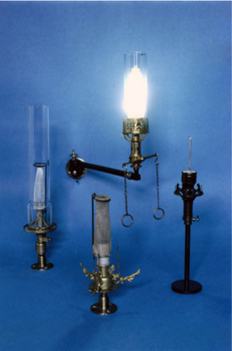
Unlike coal gas, acetylene burns with a very bright white ame. Although electricity was starting to become more commonly used it was very expensive and acetylene offered a cheaper alternative for domestic lighting. Thus, by 1899 there were over 250,000 acetylene gas jets in Germany alone. The reaction of calcium carbide to form acetylene was used in a variety of portable lamps. These so-called carbide lamps were used in slate, copper and tin mines, and were also used extensively as headlights in early automobiles and bikes (Figure \(\PageIndex{4}\).20).

Unfortunately for acetylene there was one discovery and one economic change that brought the use of acetylene as a light source to an end. In 1893 Auer von Welsbach (Figure \(\PageIndex{4}\).21) invented the gas mantel (Figure \(\PageIndex{4}\).22). By the impregnation of silk or cotton with a mixture of thorium dioxide and cerium(IV) oxide (99:1), and using this in combination with gas he was able to produce a very white ame.
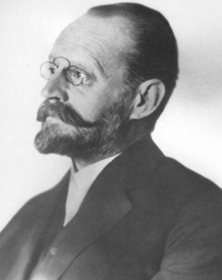
The other impact on acetylene, was that by 1905 the cost of electricity was significantly lower, and as a consequence the price of CaC2 dropped to 30%. There were stockpiles of calcium carbide all over Europe and America. This may have been the end of calcium carbide's usefulness, however, in 1895 Heinrich Caro (Figure \(\PageIndex{4}\).23) and Adolf Frank (Figure \(\PageIndex{4}\).24), at the German chemical giant Badische Anilin- und Soda-Fabrik (BASF), were trying to make hydrogen cyanide (HCN) to use in its color dye business. In 1898, one of their colleagues demonstrated that what was actually produced during the reaction at temperatures exceeding 1000 °C was not cyanide, as they had hoped. It turned out that what Caro and Frank had found was that that when calcium carbide is reacted with nitrogen at 1000 ◦C it forms calcium cyanamide (CaCN2), (4.2.6). The cyanamide anion has the structure [N=C=N]2-.
\[ CaC_2 + N_2 \rightarrow CaCN_2 + C \]
In contact with water calcium cyanamide decomposes and liberates ammonia:
\[ CaCN_2 + 3 H_2O \rightarrow 2 NH_3 + CaCO_3 \]
As such, CaCN2 is an excellent solid fertilizer that is readily plowed into the soil. By 1908 calcium cyanamide was also found to be a plant protection agent, which, at a time when all weed control was performed mechanically, represented a great step forward. Consequently, the output of calcium cyanamide grew enormously. In 1910, 30,000 tons were produced, but in 1928, global production had reached 1.2 million tons. After a temporary decline, demand has again risen in recent years owing to the ban on several pesticides due to the environmental damage they cause. Even after 100 years of use, no harmful long-term effects to the earth or environment have been observed, nor have weeds or pests developed a resistance to calcium cyanamide.
Bibliography
- N.-G. Vannerberg, Acta Chem. Scand., 1962, 16, 1212.
- M. A. Bredig, J. Am. Chem. Soc., 1942, 64, 1730.
- Y. Yamamoto, K. Kinoshita, K. Tamaru, and T. Yamanaka, Bull. Chem. Soc. Japan, 1958, 31, 501.
Portland Cement
Chemical Composition of Portland Cement
There are four chief minerals present in a Portland cement grain: tricalcium silicate (Ca3SiO5), dicalcium silicate (Ca2SiO4), tricalcium aluminate (Ca3Al2O5) and calcium aluminoferrite (Ca4AlnFe2-nO7). The formula of each of these minerals can be broken down into the basic calcium, silicon, aluminum and iron oxides (Table \(\PageIndex{4}\).6). Cement chemists use abbreviated nomenclature based on oxides of various elements to indicate chemical formulae of relevant species, i.e., C = CaO, S = SiO2, A = Al2O3, F = Fe2O3. Hence, traditional cement nomenclature abbreviates each oxide as shown in Table \(\PageIndex{4}\).6.
| Mineral | Chemical formula | Oxide composition | Abbreviation |
|---|---|---|---|
| Tricalcium silicate (alite) | Ca3SiO5 | 3CaO.SiO2 | C3S |
| Dicalcium silicate (belite) | Ca2SiO4 | 2CaO.SiO2 | C2S |
| Tricalcium aluminate | Ca3Al2O4 | 3CaO.Al2O3 | C3A |
| Tetracalcium aluminoferrite | Ca4AlnFe2-nO7 | 4CaO.AlnFe2-nO3 | C4AF |
The composition of cement is varied depending on the application. A typical example of cement contains 5070% C3S, 1530% C2S, 510% C3A, 515% C4AF, and 38% other additives or minerals (such as oxides of calcium and magnesium). It is the hydration of the calcium silicate, aluminate, and aluminoferrite minerals that causes the hardening, or setting, of cement. The ratio of C3S to C2S helps to determine how fast the cement will set, with faster setting occurring with higher C3S contents. Lower C3A content promotes resistance to sulfates. Higher amounts of ferrite lead to slower hydration. The ferrite phase causes the brownish gray color in cements, so that white cements (i.e., those that are low in C4AF) are often used for aesthetic purposes.
The calcium aluminoferrite (C4AF) forms a continuous phase around the other mineral crystallites, as the iron containing species act as a fluxing agent in the rotary kiln during cement production and are the last to solidify around the others. Figure \(\PageIndex{4}\).25 shows a typical cement grain.
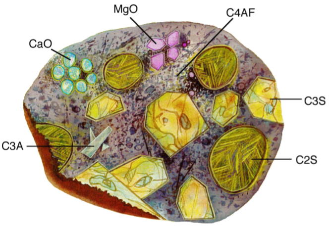
It is worth noting that a given cement grain will not have the same size or even necessarily contain all the same minerals as the next grain. The heterogeneity exists not only within a given particle, but extends from grain to grain, batch-to-batch, plant to plant.
Bibliography
- H. F. W. Taylor, Cement Chemistry, 2nd Ed., Academic Press, London (1997).
Manufacture of Portland Cement
Portland Cement is manufactured by heating calcium carbonate and clay or shale in a kiln. During this process the calcium carbonate is converted to calcium oxide (also known as lime) and the clay minerals decompose to yield dicalcium silicate (Ca2SiO4, C2S) and other inorganic oxides such as aluminate and ferrite. Further heating melts the aluminate and ferrite phases. The lime reacts with dicalcium silicate to from tricalcium silicate (Ca3SiO5, C3S). As the mixture is cooled, tricalcium aluminate (Ca3Al2O6, C3A) and tetracalcium aluminoferrite (Ca4AlnFe2-nO7, C4AF) crystallize from the melt and tricalcium silicate and the remaining dicalcium silicate undergo phase transitions. These four minerals (C3S, C2S, C3A, and C4AF) comprise the bulk of most cement mixtures. Initially Portland cement production was carried out in a furnace, however, technological developments such as the rotary kiln have enhanced production capabilities and allowed cement to become one of the most widely used construction materials.
Cement plants generally produce various grades of cement by two processes, referred to as either the wet or dry process. The dry process uses a pneumatic kiln system which uses superheated air to convert raw materials to cement, whereas the wet process slurries the raw materials in water in preparation for conversion to cement. Cement manufacturers due to its higher energy efficiency generally favor the dry process, but the wet process tends to produce cement with properties more palatable to the energy services industry. The American Petroleum Institute (API) Class H cement used in energy service applications is produced by the wet process, and thus will be the focus of the following discussion.
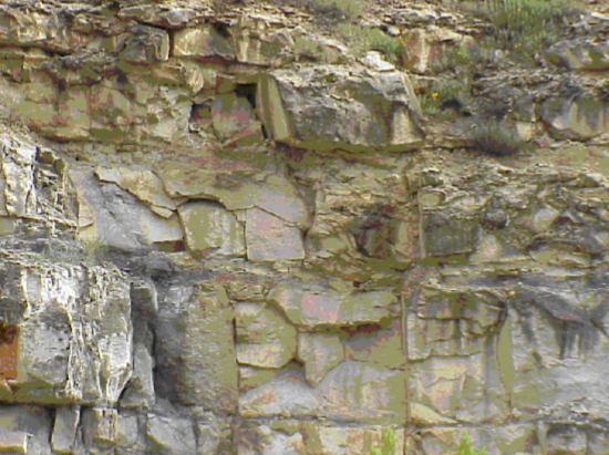
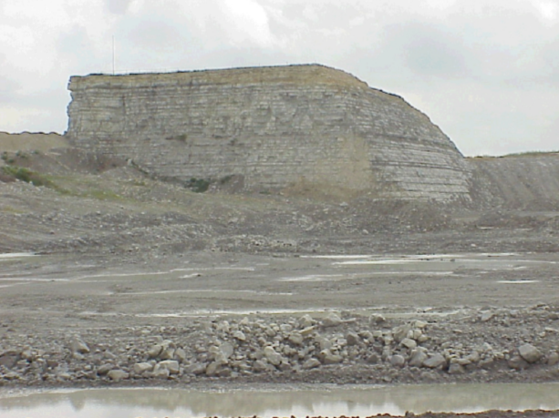
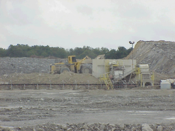
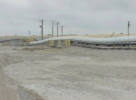
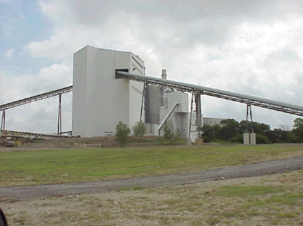
The cement manufacturing process begins at the quarry (Figure \(\PageIndex{4}\).26), where limestone formations are ripped and crushed in two crushers to a mean particle size of 4". The quarry formation is not entirely limestone, and no attempt is made to isolate the limestone from the other minerals. On the contrary, the rippers act to blend in the impurity minerals as evenly as is feasible while still maintaining an acceptable limestone content so as not to waste the formation. This is accomplished by ripping the formation face at a 45◦ (Figure \(\PageIndex{4}\).27). The rock is quality controlled via mobile X-ray fluorescence (XRF) spectroscopy (Figure \(\PageIndex{4}\).28) at the starting point of a mobile covered conveyor belt system (Figure \(\PageIndex{4}\).29), which transports the material to a dome storage unit (Figure \(\PageIndex{4}\).30).
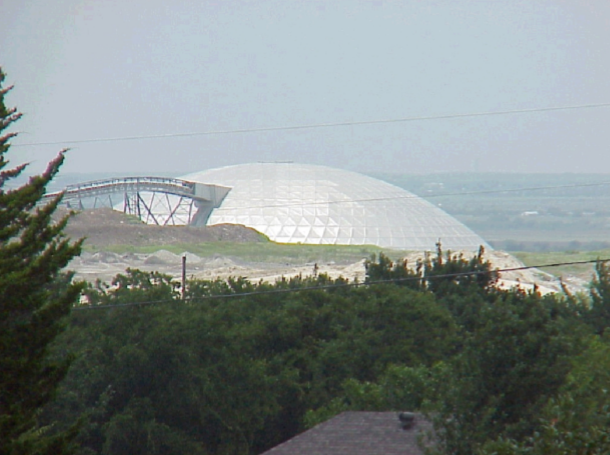
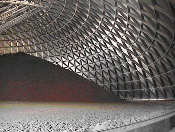
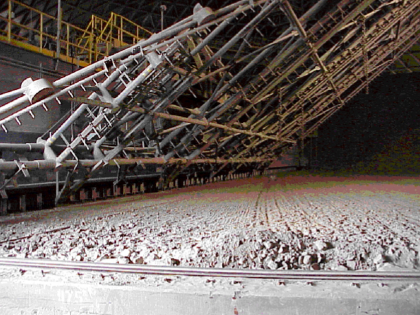
The dome storage unit has a capacity of 60 kilotons, and is filled by dispensing the rock from the conveyor at the top of the dome into a pile built in a circular pattern (Figure \(\PageIndex{4}\).31). The rock is reclaimed from storage via a raking device (Figure \(\PageIndex{4}\).32) that grates over the pile at the natural angle of material slide. The raked material slides to the base of the raking unit, where a second conveyor system transfers material to either of two limestone buffer bins (Figure \(\PageIndex{4}\).33), each of which is dedicated to a particular kiln process. There is an additional buffer bin for mill scale from a nearby steel plant, as well as a buffer bin for sand. It is worth noting at this point that the mill scale from the steel plant contains significant levels of boron, which acts as an innate retarder and seems to affect adversely, though not overly severely, the early compressive strength development when compared to cement from other plants.
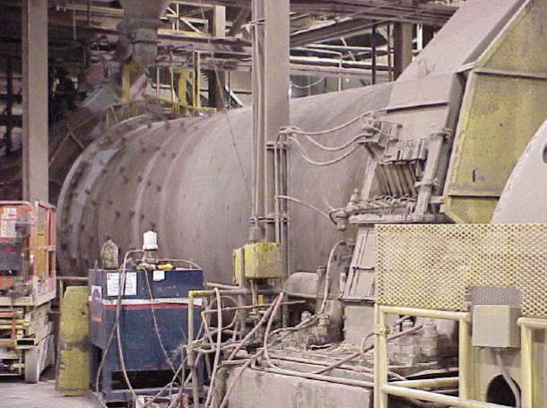
Material leaving the buffer bins is monitored for elemental composition via XRF and feed rates are adjusted for maintaining proper ow of calcium, silicon, aluminum, and iron. The raw materials are carried to ball mills (Figure \(\PageIndex{4}\).34) for grinding to ne powder, which is then mixed with water. The resulting slurry is then sent to the rotary kiln for burning (Figure \(\PageIndex{4}\).35), or transformation into cement clinker.
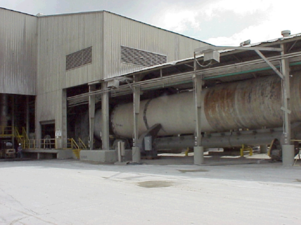
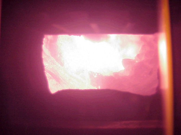
The kilns are red to an internal material temperature of 2700 ◦F (Figure \(\PageIndex{4}\).36) with a fuel of nely ground coal, natural gas, and/or various waste materials. Around fifty percent of the energy expenditure in the wet kiln process is dedicated to evaporating the water from the slurry, in contrast to the dry process, which spends most of its energy on the calcining process. Since the dry process only requires approximately half the energy of the wet process, it is generally more attractive to cement manufacturers. Unfortunately, the dry process in current use produces poor API Class H cement. A fuller understanding of the differences in cement synthesis via the two processes could lead to the development of a more effective dry synthesis of Class H cements, but that is beyond the scope of this work.
After the clinker leaves the kiln, it enters a cooler that uses pressurized air to cool the clinker. The energy absorbed by the air in the cooler serves to pre-heat the air for feed into the kiln. The cooled clinker is then taken to storage to await nal grinding with approximately ve percent gypsum by weight. After grinding to the specied fineness, the nal cement powder is pneumatically transferred to storage silos until it is shipped to the customer.
Quality control of the clinker and nal powder is handled via an automated X-ray diffraction/X-ray fluorescence (XRD/XRF) system, simple wet chemical analyses, simple optical microscopy, and periodic performance tests, including compressive strength and thickening time. This entire process results in the heterogeneous nanocomposite of calcium silicate and aluminate particles, among other materials, which make up a typical cement grain.
Hydration of Portland Cement
The addition of water to dry cement powder results in a thin cement slurry that can be easily manipulated and cast into different shapes. In time, the slurry sets and develops strength through a series of hydration reactions. Hydration of cement is not linear through time, it proceeds very slowly at first, allowing the thin mixture to be properly placed before hardening. The chemical reactions that cause the delay in hardening are not completely understood; however, they are critical to developing a rational methodology for the control of cement setting.
Tri- and di-calcium silicates
The tri- and di-calcium silicates (C3S and C2S, respectively) comprise over 80% by weight of most cement. It is known that C3S is the most important phase in cement for strength development during the first month, while C2S reacts much more slowly, and contributes to the long-term strength of the cement. Both the silicate phases react with water as shown below to form calcium hydroxide and a rigid calcium-silicate hydrate gel, CSH, (4.2.7) and (4.2.8).
\[ 2 (CaO)_3(SiO_2) + 7 H_2O \rightarrow (CaO)_3(SiO_2)_24(H_2O) + 3 CA(OH)_2 \]
\[ 2 (CaO)_2(SiO_2) + 5 H_2O \rightarrow (CaO)_3(SiO_2)_24(H_2O) + Ca(OH)_2 \]
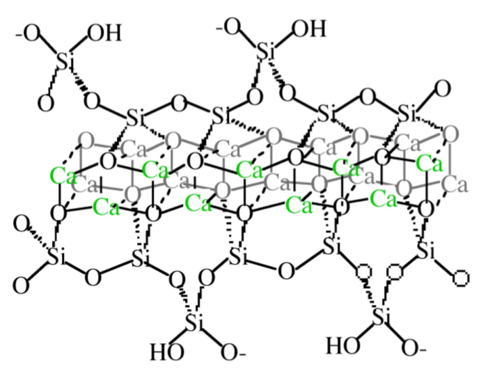
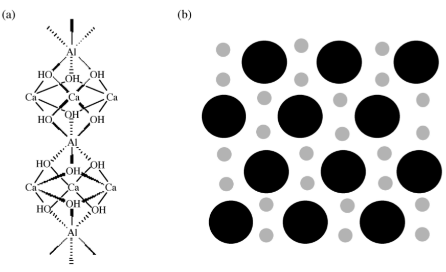
The detailed structure of CSH is not completely known, however it is generally agreed upon that it consists of condensed silicate tetrahedrally sharing oxygen atoms with a central, calcium hydroxide-like CaO2 layer. Calcium hydroxide consists of hexagonal layers of octahedrally coordinated calcium atoms and tetrahedrally coordinated oxygen atoms. Taylor has proposed that the structure is most similar to either Tobermorite or Jennite, both of which share a skeletal silicate chain Figure \(\PageIndex{4}\).37.
Although the precise mechanism of C3S hydration is unclear, the kinetics of hydration is well known. The hydration of the calcium silicates proceeds via four distinct phases as shown in Figure \(\PageIndex{4}\).38. The first 15-20 minutes, termed the pre-induction period (Figure \(\PageIndex{4}\).38a), is marked by rapid heat evolution. During this period calcium and hydroxyl ions are released into the solution. The next, and perhaps most important, phase is the induction period (Figure \(\PageIndex{4}\).38b), which is characterized by very slow reactivity. During this phase, calcium oxide continues to dissolve producing a pH near 12.5. The chemical reactions that cause the induction period are not precisely known; however, it is clear that some form of an activation barrier must be overcome before hydration can continue. It has been suggested that in pure C3S, the induction period may be the length of time it takes for CSH to begin nucleation, which may be linked to the amount of time required for calcium ions to become supersaturated in solution. Alternatively, the induction period may be caused by the development of a small amount of an impermeable calcium-silicon-hydrate (CSH) gel at the surface of the particles, which slows down the migration of water to the inorganic oxides. The initial Ca/Si ratio at the surface of the particles is near 3. As calcium ions dissolve out of this CSH gel, the Ca/Si ratio in the gel becomes 0.8-1.5. This change in Ca/Si ratio corresponds to a change in gel permeability, and may indicate an entirely new mechanism for CSH formation. As the initial CSH gel is transformed into the more permeable layer, hydration continues and the induction period gives way to the third phase of hydration, the acceleratory period (Figure \(\PageIndex{4}\).38c).
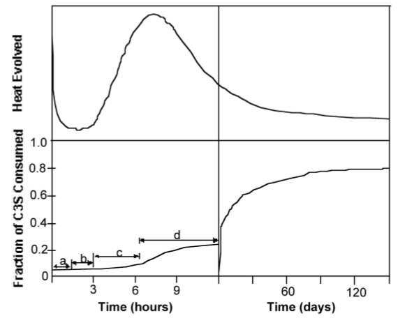
After ca. 3 hours of hydration, the rate of CSH formation increases with the amount of CSH formed. Solidification of the paste, called setting, occurs near the end of the third period. The fourth stage (Figure \(\PageIndex{4}\).38d) is the deceleratory period in which hydration slowly continues hardening the solid cement until the reaction is complete. The rate of hydration in this phase is determined either by the slow migration of water through CSH to the inner, unhydrated regions of the particles, or by the migration of H+ through the CSH to the anhydrous CaO and SiO2, and the migration of Ca2+ and Si4+ to the OH- ions left in solution.
Calcium aluminate and ferrite
In spite of the fact that the aluminate and ferrite phases comprise less than 20% of the bulk of cement, their reactions are very important in cement and dramatically affect the hydration of the calcium silicate phases, see below. Relative to C3S, the hydration of C3A is very fast. In the absence of any additives, C3A reacts with water to form two intermediate hexagonal phases, C2AH8 and C4AH13, (4.2.9). The structure of C2AH8 is not precisely known, but C4AH13 has a layered structure based on the calcium hydroxide structure, in which one out of every three Ca2+ is replaced by either an Al3+ or Fe3+ with an OH- anion in the interlayer space to balance the charge. All of the aluminum in C4AH13 is octahedral. C2AH8 and C4AH13 are meta-stable phases that spontaneously transform into the fully hydrated, thermodynamically stable cubic phase, C3AH6, (4.2.10). In C3A, aluminum coordination is tetrahedral. The structure consists of rings of aluminum tetrahedrally linked through bridging oxygen atoms, which slightly distorts the aluminum environment. In C3AH6, aluminum exists as highly symmetrical, octahedral Al(OH)6 units.
\[2 (CaO)_3(Al_2O_3) + 21 H_2O \rightarrow (CaO)_4(Al_2O_3) \cdot 13(H_2O) + (CaO)_2(Al_2O_3) \cdot 8(H_2O) \]
\[(CaO)_4(Al_2O_3)\cdot 13(H_2O) + (CaO)_2(Al-2O_3) \cdot 8(H_2O) \rightarrow 2 (CaO)_3(Al_2O_3) \cdot 6(H_2O) + 9 H_2O \]
If the very rapid and exothermic hydration of C3A is allowed to proceed unhindered in cement, then the setting occurs too quickly and the cement does not develop strength. Therefore, gypsum [calcium sulfate dihydrate, CaSO4·2(H2O)] is added to slow down the C3A hydration. In the presence of gypsum, tricalcium aluminate forms ettringite, [Ca3Al(OH)6.12(H2O)]2.(SO4)3.2(H2O), (4.2.11), which can also be written as C3A.3(CaSO4).32(H2O). Ettringite grows as columns of calcium, aluminum and oxygen surrounded by water and sulfate ions, as shown in Figure \(\PageIndex{4}\).39.
\[ (CaO)_4(Al_2O_3) + 3 CaSO_4 \cdot 2(H_2O) + 26 H_2O \rightarrow (CaO)_3(Al_2O_3)(CaSO_4)_3 \cdot 32(H_2O) \]
Tetracalcium aluminoferrite (C4AF) reacts much like C3A, i.e., forming ettringite in the presence of gypsum. However, hydration the ferrite phase is much slower than hydration of C3A, and water is observed to bead up on the surface of C4AF particles. This may be due to the fact that iron is not as free to migrate in the pastes as aluminum, which may cause the formation of a less permeable iron rich layer at the surface of the C4AF particles and isolated regions of iron hydroxide. In cement, if there is insufficient gypsum to convert all of the C4AF to ettringite, then an iron-rich gel forms at the surface of the silicate particles which is proposed to slow down their hydration.
Portland Cement
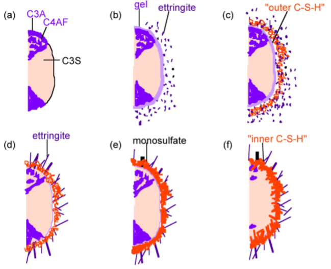
The hydration of cement is obviously far more complex than the sum of the hydration reactions of the individual minerals. The typical depiction of a cement grain involves larger silicate particles surrounded by the much smaller C3A and C4AF particles. The setting (hydration) of cement can be broken down into several distinct periods. The more reactive aluminate and ferrite phases react first, and these reactions dramatically affect the hydration of the silicate phase. Scrivener and Pratt used TEM to develop the widely accepted model depicted in Figure \(\PageIndex{4}\).40.
In the first few minutes of hydration (Figure \(\PageIndex{4}\).40b), the aluminum and iron phases react with gypsum to form an amorphous gel at the surface of the cement grains and short rods of ettringite grow. After this initial period of reactivity, cement hydration slows down and the induction period begins. After about 3 hours of hydration, the induction period ends and the acceleratory period begins. During the period from 3 to 24 hours, about 30% of cement reacts to form calcium hydroxide and CSH. The development of CSH in this period occurs in 2 phases. After ca. 10 hours hydration (Figure \(\PageIndex{4}\).40c), C3S has produced outer CSH, which grows out from the ettringite rods rather than directly out from the surface of the C3S particles. Therefore, in the initial phase of the reaction, the silicate ions must migrate through the aluminum and iron rich phase to form the CSH. In the latter part of the acceleratory period, after 18 hours of hydration, C3A continues to react with gypsum, forming longer ettringite rods (Figure \(\PageIndex{4}\).40d). This network of ettringite and CSH appears to form a hydrating shell about 1 µm from the surface of anhydrous C3S. A small amount of inner CSH forms inside this shell. After 13 days of hydration, reactions slow down and the deceleratory period begins (Figure \(\PageIndex{4}\).40e). C3A reacts with ettringite to form some monosulfate. Inner CSH continues to grow near the C3S surface, narrowing the 1 µm gap between the hydrating shell and anhydrous C3S. The rate of hydration is likely to depend on the diusion rate of water or ions to the anhydrous surface. After 2 weeks hydration (Figure \(\PageIndex{4}\).40f), the gap between the hydrating shell and the grain is completely filled with CSH. The original, outer CSH becomes more fibrous.
Bibliography
- H. F. W. Taylor, Cement Chemistry, 2nd Ed., Academic Press, London (1997).
- H. F. W. Taylor, J. Am. Ceram. Soc., 1986, 69, 464.
- V. S. Ramanchandran, R.F. Feldman, and J. J. Beaudoin, Concrete Science, Heyden and Son Ltd., Philadelphia, PA, 1981.
- H. N. Stein and J. Stevels, J. App. Chem., 1964, 14, 338.
- M. Grutzeck, S. Kwan, J. Thompson, and A. Benesi, J. Mater. Sci. Lett., 1999, 18, 217.
- V. S. Ramachandran, Concrete Admixtures Handbook, 2nd Edition, Noyes Publications, New Jersey (1995).
- K. L. Scrivener and P. L. Pratt, Mater. Res. Soc. Symp. Proc., 1984, 31, 351.
Hydration Inhibition of Portland Cement
In the oil industry, Portland cement supports boreholes of ever increasing depth. This application requires a high degree of control over the setting kinetics to allow the cement to be pumped down in a liquid form. A number of chemical inhibitors are employed to delay the setting time. The ideal inhibitor for oil well cementing would predictably delay the setting of cement, and then suddenly allow hydration to continue at a rapid rate.
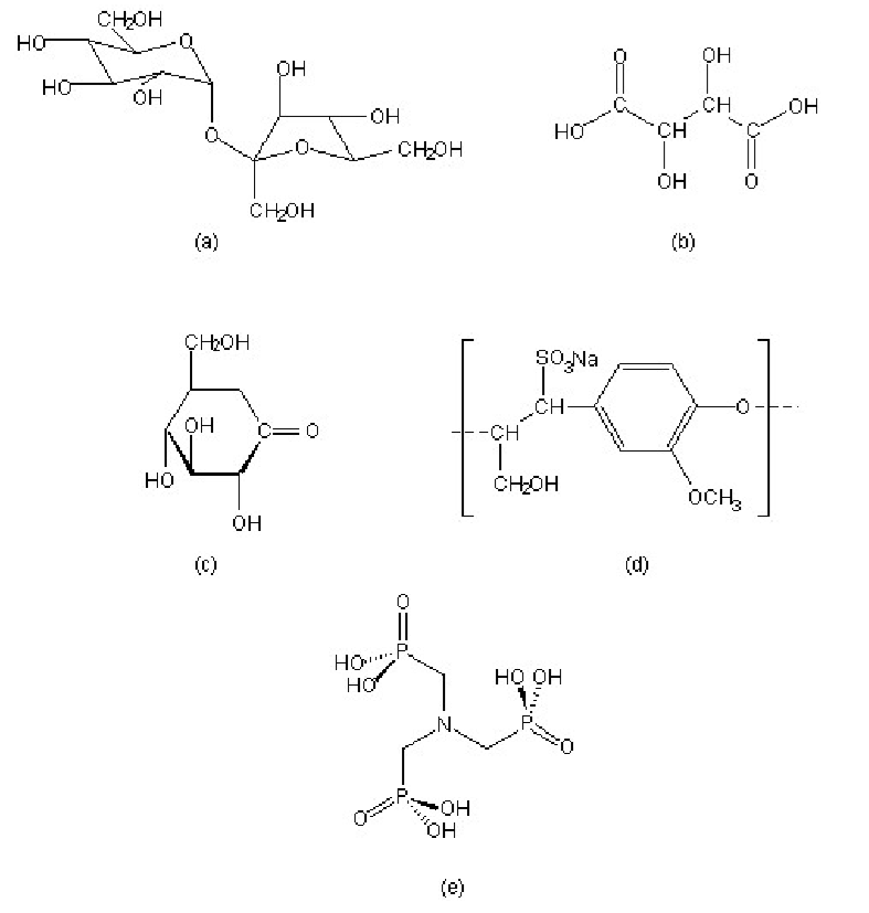
A wide range of compounds show set inhibition of the hydration of Portland cement. Some common examples include, sucrose, tartaric acid, gluconic acid δ-lactone, lignosulfonate, and organic phosphonic acids, in particular nitrilo-tris(methylene)phosphonic acid (H6ntmp). The structures of these retarders are shown in.
In spite of the fact that the science of cement hydration inhibition has been investigated for over 40 years, the mechanistic details are still the subject of much speculation. There are ve primary models for cement hydration inhibition: calcium complexation, nucleation poisoning, surface adsorption, protective coating/osmotic bursting, and dissolution-precipitation. A summary of the characteristic behavior of selected retarders is shown in Table \(\PageIndex{4}\).7.
| Retarder |
Characteristic behavior |
|---|---|
| sucrose | Ca binding, acts directly on silicates, accelerates ettringite formation |
| tartaric acid | acts via calcium complexation and calcium tartrate coating, inhibits ettringite formation |
| lignosulfonate | accelerates ettringite formation, calcium becomes incorporated into the polymer matrix during hydration, forms a diffusion barrier |
| nitrilo-tris(methylene)phosphonic acid (H6ntmp) |
promotes Ca dissolution, forms [Ca(H6ntmp)], heterogeneous nucleation on aluminates creates a protective coating around the grain |
Calcium complexation
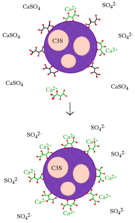
Inhibition by calcium complexation relies largely on the requirement that small calcium oxide/hydroxide templates must form in the pore water of cement pastes before silicate tetrahedra can condense into dimeric and oligomeric silicates to form CSH. Calcium complexation involves either removing calcium from solution by forming insoluble salts, or chelating calcium in solution. Calcium complexation lowers the amount of calcium effectively in solution, delaying the time to Ca(OH)2 super-saturation and preventing precipitation of the necessary templates. Simple calcium complexation should dramatically increase the amount of Si(OH)4 tetrahedra in solution, and indeed this is observed with most retarders. However, if the retarder were acting solely by calcium complexation, then one molecule of retarder would be required per calcium ion in solution, and good inhibitors are used in much smaller quantities, on the order of 0.1-2% by weight of cement. In addition, there is no simple correlation between either calcium binding strength or calcium salt solubility and retarding ability. Yet it has been shown that in pure systems, i.e., of C3S and C2S, that the lime concentration in solutions is the most important factor in determining the precipitation of CSH. Therefore, although calcium complexation must play some role in inhibition, other mechanisms of inhibition must be at work as well. An example of a retarder that operates primarily through calcium complexation is tartaric acid, however, the formation of insoluble calcium tartrate on cement grains suggest that dissolution/precipitation occurs in addition (Figure \(\PageIndex{4}\).42).
Nucleation poisoning
As with calcium complexation, nucleation poisoning must rely on the formation of small calcium oxide/hydroxide templates in the pore water of cement pastes before silicate tetrahedra can condense into dimeric and oligomeric silicates to form CSH. Inhibition by nucleation poisoning is where the retarder blocks the growth of CSH or Ca(OH)2 crystals through inhibiting agglomerates of calcium ions from forming the necessary hexagonal pattern. Nucleation inhibitors act on the surface of small clusters, therefore, less than one molecule of retarder per calcium ion is required to produce dramatic results. This type of inhibition also results in an increase in the amount of silicate ions in solution, as condensation of silicate chains onto calcium oxide templates to form the CSH is inhibited. As a retarder sucrose acts via nucleation poisoning/surface adsorption.
Surface adsorption
Surface adsorption of inhibitors directly onto the surface of either the anhydrous or (more likely) the partially hydrated mineral surfaces blocks future reactions with water. In addition, if such inhibitors are large and anionic, then they produce a negative charge at the surface of the cement grains, causing the grains to repel each other thereby reducing inter-particle interactions. Lignosulfonates are typical of retarders that act via surface adsorption.
Protective coating/osmotic bursting
The formation of a protective coating with its subsequent bursting due to the build up of osmotic pressure was originally posited to explain the existence of the induction period in C3S and cement hydration, however it may be applied to inhibition in general. In this mechanism, a semi-permeable layer at the surface of the cement grain forms and slows down the migration of water and lengthens the induction period. Osmosis will drive water through the semi-permeable membrane towards the unhydrated mineral, and eventually the ow of water creates higher pressure inside the protective coating and the layer bursts. Hydration is then allowed to continue at a normal rate.
Dissolution-precipitation
A detailed study of several retarders (in particular the organic phophonates) has shown that the actually accelerate certain stages of the hydration process. This is unexpected since the phosphonates have been termed super retarders, due to their increased effect on cement hydration relative to the effect of conventional retarders. So how is it that a retarder can be so efficient at hydration inhibition at the same time as accelerating the process? The ability of phosphonates to retard cement setting is due to the lengthening the induction period, without slowing down the time it takes for setting to occur (once the acceleratory period has begun).
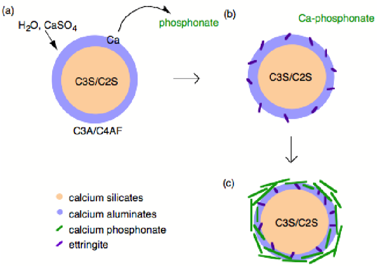
Phosphonates are known to complex calcium and other M2+ cations, poison the nucleation and growth of barium sulfate crystals, and inhibit the hydration of Fe2O3 and Al2O3 surfaces via direct surface adsorption, thus it was assumed that with regard to cement hydration inhibition occurred by one of these mechanism. However, the mechanism by which phosphonates inhibit cement hydration consists of two steps. First dissolution, whereby calcium is extracted from the surface of the cement grains (Figure \(\PageIndex{4}\).43a) exposing the aluminum rich surface to enhanced (catalyzes) hydration and ettringite formation (Figure \(\PageIndex{4}\).43b). Second precipitation, whereby the soluble calcium-phosphonate oligomerizes either in solution or on the hydrate surface to form an insoluble polymeric Ca-phosphonate (Figure \(\PageIndex{4}\).43c). The Ca-phosphonate material binds to the surface of the cement grains inhibiting further hydration by acting as a diffusion barrier to water as well as a nucleation inhibitor.
Bibliography
- N. Thomas and J. Birchall, Cement and Concrete Research, 1983, 13, 830.
- D. Double, Phil. Trans. R. Soc. London, 1983, A30, 53.
- M. Bishop, S. G. Bott, and A. R. Barron, Chem. Mater., 2003, 15, 3074.
- M. Bishop and A. R. Barron, Ind. Eng. Chem. Res., 2006, 45, 7042.