
Flash Analog to Digital Conversion
- Page ID
- 60145

The first type of analog to digital coverter (henceforth, ADC) we will consider is the fastest: the aptly-named flash converter. This converter uses comparators to determine what potential is instantaneously present on an input, and just as instantaneously to provide a digital output instantaneously reporting the value. No sample and hold is employed.
To keep the situation simple, let's design a 2 bit straight binary flash converter. The output codes can be 00, 01, 10, or 11. If the full range of the converter is 5 V, then the transitions between the codes should be at 1/4, 1/2, and 3/4 of full scale or 1.25 V, 2.5 V, and 3.75 V. If the instantaneous potential is, say, 1.35 V, the output should be 01. We can generate the reference potentials with a resistive divider, and use one comparator for each reference level. That means the analog section of the circuit looks like this:
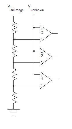
The switching speed is the speed of the comparators, and that can be extremely fast as long as the input capacitance of the comparators is small.
There are 3 comparators, the outputs of which need to be encoded into 2 bits. The most significant bit (MSB) gets set to 1 as long as the signal is at least 2.5 V, while the least significant bit (LSB) gets set if either the 3.75 V comparator output is positive or the 1.25 V comparator is ON and the 2.5 V comparator is OFF. Adding logic gates (the pointed output gate is OR, the rounded end is AND, and a small circle indicates logical NOT), the full circuit is:

To get an encoding of 4 output levels, we required 3 comparators. How many comparators would we need for 256 output levels (8 bits)?
As the number of comparators increases, one rapidly reaches a point of diminishing returns. Every time one wishes to add one more bit to the ADC output, one doubles the number of comparators. Since each comparator has some input capacitance (and the wiring feeding the comparators has capacitance as well!), the maximum speed drops because RC increases. This collides with the greater settling time needed to improve the number of bits of accuracy. Thus, beyond 8 bits, flash converters face severe limitations. Nevertheless, in the fastest digital instruments, in high speed cameras, and in communications systems, digitization rates of over 1 GHz have been realized, while several hundred MHz digitization is routine. Using the arguments we have already made, assuming a source resistance of 50Ω (quite common), input capacitance for each comparator of 1 pF, and ignoring speed limitations in the comparator (dream on!), the fastest a flash converter can digitize is:
| Number of bits | Maximum Digitization Rate (Hz) |
|---|---|
| 1 |
29 GHz
|
| 4 |
1.8 GHz
|
| 8 |
450 MHz
|
| 12 |
200 MHz
|
| 16 |
113 MHz
|
Let's critically consider this table. Silicon transistors can not switch at 29 GHz; the fastest switches can run at less than 10 GHz. GaAs can reach 30 GHz, but is not commonly used in consumer electronics. For the highest numbers of bits (>8), there is an additional error source that we haven't yet considered. A flash converter is no more accurate than the resistors in the divider chain. To be useful, a 16 bit converter needs the divider chain to be accurate to 1 part in 65536. The best resistors one can purchase are ~ 0.01% accurate at a single temperature (and change resistance by 5 parts per million per degree Celsius). 0.01% is about 12 bit resolution. This hints at a more general problem: high resolution simply can't count on precision of resistors to set digitization precision. We ill find that some of the other ADC designs depend on component precision, others not.