
6.2B: Electrothermal Atomization – Graphite Furnace
- Page ID
- 111875

The graphite furnace, which is pictured in Figure \(\PageIndex{3}\), is a small, hollow graphite tube about 2 Inches long by ¼ inch in diameter with a hole in the top. Graphite furnaces are used for atomic absorbance measurements. Radiation from the source shines through the tube to the detector. A small volume of sample (typically \(0.5\) to \(10 \mu l\)) is introduced through the hole into the tube either through the use of a micropipette or a spray system. The entire furnace system is maintained under an argon atmosphere.
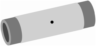
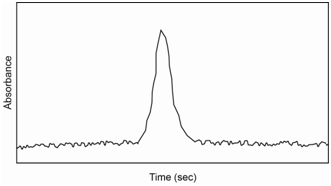
After introduction of the sample into the furnace, a three step heating process is followed. The first step (heating to about 100oC) evaporates the solvent. The second (heating to about 800oC) ashes the sample to a metal power or metal oxide. The third (heating to between 2,000-3,000oC) atomizes the sample. The first two steps are on the order of seconds to a minute. The third step occurs over a few milliseconds to seconds. The atomization step essentially creates a “puff” of gas phase atoms in the furnace and the absorbance is measured during this time, yielding a signal similar to what is shown in Figure \(\PageIndex{4}\). This “puff” of atoms only occurs over a second or so before the sample is swept from the furnace. The area under the curve is integrated and related back to the concentration through the use of a standard curve.
What are the relative advantages and disadvantages of using a flame or furnace as an atomization source?
Sample size: One obvious difference is the amount of sample needed for the analysis. Use of the flame requires establishing a steady state system in which sample is introduced into the flame. A flame analysis usually requires about 3-5 ml of sample for the measurement. Triplicate measurements on a furnace require less than 50 ul of sample. In cases where only small amounts of sample are available, the furnace is the obvious choice.
Sensitivity: The furnace has a distinct advantage over the flame with regards to the sensitivity and limits of detection. One reason is that the entire sample is put into the furnace whereas only 2% of the sample makes it into the flame. Another is that the furnace integrates signal over the “puff” of atoms whereas the flame involves establishment of a steady state reading. A disadvantage of the flame is that atoms only spend a brief amount of time (about 10-4 seconds) in the optical path. Finally, for certain elements, the atomization efficiency (what percentage of the elements end up as ground state atoms suitable for absorption of energy) is higher for the furnace than the flame.
Reproducibility: The flame has a distinct advantage over the furnace in terms of reproducibility of measurements. Remember that more reproducible measurements mean that there is better precision. One concern is whether the amount of sample being introduced to the atomization source is reproducible. Even though we often use micropipettes and do not question their accuracy and reproducibility, they can get out of calibration and have some degree of irreproducibility from injection to injection. Introduction of the sample into the flame tends to be a more reproducible process.
Another concern with atomic methods is the presence of matrix effects. The matrix is everything else in the sample besides the species being analyzed. Atomic methods are highly susceptible to matrix effects. Matrix effects can enhance or diminish the response in atomic methods. For example, when using a flame, the response for the same concentration of a metal in a sample where water is the solvent may be different when compared to a sample with a large percentage of alcohol as the solvent (e.g., a hard liquor). One difference is that alcohol burns so it may alter the temperature of the flame. Another is that alcohol has a different surface tension than water so the nebulization efficiency and production of smaller aerosol particles may change. Another example of a matrix effect would be the presence of a ligand in the sample that leads to the formation of a non-volatile metal complex. This complex may not be as easy to vaporize and then atomize. While it is somewhat sample dependent, matrix effects are more variable with a furnace than the flame. An issue that comes up with the furnace that does not exist in the flame is the condition of the interior walls of the furnace. These walls “age” as repeated samples are taken through the evaporation/ash/atomize steps and the atomization efficiency changes as the walls age. The furnace may also exhibit memory effects from run to run because not all of the material may be completely removed from the furnace. Evaporation of the solvent in the furnace may lead to the formation of salt crystals that rupture with enough force to spew material out the openings in the furnace during the ashing step. This observation is why some manufacturers have developed spray systems that spread the sample in a thinner film over more of the interior surface than would occur if adding a drop from a micropipette. These various processes that can occur in the furnace often lead to less reproducibility and reduced precision (relative precision on the order of 5-10%) when compared to flame (relative precision of 1% or better) atomization.