6.3: Rolling Molecules on Surfaces Under STM Imaging
- Page ID
- 55902

Introduction to Surface Motions at the Molecular Level
As single molecule imaging methods such as scanning tunneling microscope (STM), atomic force microscope (AFM), and transmission electron microscope (TEM) developed in the past decades, scientists have gained powerful tools to explore molecular structures and behaviors in previously unknown areas. Among these imaging methods, STM is probably the most suitable one to observe detail at molecular level. STM can operate in a wide range of conditions, provides very high resolution, and able to manipulate molecular motions with the tip. An interesting early example came from IBM in 1990, in which the STM was used to position individual atoms for the first time, spelling out "I-B-M" in Xenon atoms. This work revealed that observation and control of single atoms and molecular motions on surfaces were possible.
The IBM work, and subsequent experiments, relied on the fact that STM tip always exerts a finite force toward an adsorbate atom that contains both van der Waals and electrostatic forces was utilized for manipulation purpose. By adjusting the position and the voltage of the tip, the interactions between the tip and the target molecule were changed. Therefore, applying/releasing force to a single atom and make it move was possible Figure \(\PageIndex{1}\).
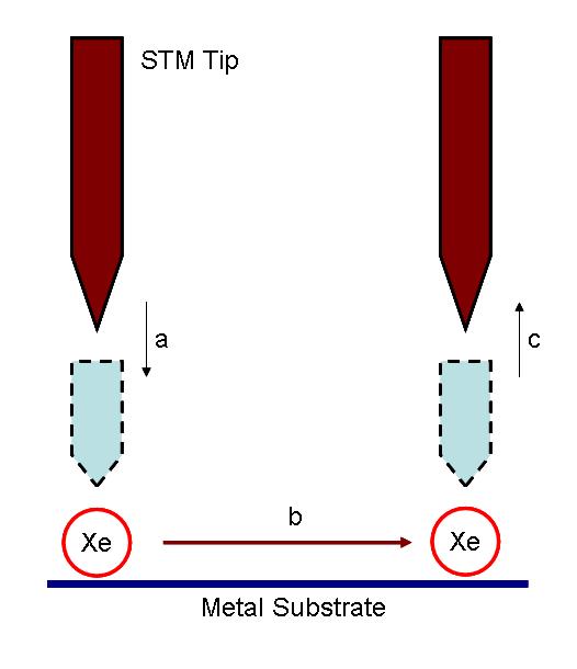
The actual positioning experiment was carried out in the following process. The nickel metal substrate was prepared by cycles of argon-ion sputtering, followed by annealing in a partial pressure of oxygen to remove surface carbon and other impurities. After the cleaning process, the sample was cooled to 4 K, and imaged with the STM to ensure the quality of surface. The nickel sample was then doped with xenon. An image of the doped sample was taken at constant-current scanning conditions. Each xenon atom appears as a located randomly 1.6 Å high bump on the surface (Figure \(\PageIndex{2}\) a). Under the imaging conditions (tip bias = 0.010 V with tunneling current 10-9 A) the interaction of the xenon with the tip is too weak to cause the position of the xenon atom to be perturbed. To move an atom, the STM tip was placed on top of the atom performing the procedure depicted in Figure \(\PageIndex{1}\) to move to its target. Repeating this process again and again led the researcher to build of the structure they desired Figure \(\PageIndex{2}\) b and c.

All motions on surfaces at the single molecule level can be described as by the following (or combination of the following) modes:
Sliding
Hopping
Rolling
Pivoting
Although the power of STM imaging has been demonstrated, imaging of molecules themselves is still often a difficult task. The successful imaging of the IBM work was attributed to selection of a heavy atom. Other synthetic organic molecules without heavy atoms are much more difficult to be imaged under STM. Determinations of the mechanism of molecular motion is another. Besides imaging methods themselves, other auxiliary methods such as DFT calculations and imaging of properly designed molecules are required to determine the mechanism by which a particular molecule moves across a surface.
Herein, we are particularly interested in surface-rolling molecules, i.e., those that are designed to roll on a surface. It is straightforward to imagine that if we want to construct (and image) surface-rolling molecules, we must think of making highly symmetrical structures. In addition, the magnitudes of interactions between the molecules and the surfaces have to be adequate; otherwise the molecules will be more susceptible to slide/hop or stick on the surfaces, instead of rolling. As a result, only very few molecules are known can roll and be detected on surfaces.
Surface Rolling of Molecules under the Manipulation of STM Tips
As described above, rolling motions are most likely to be observed on molecules having high degree of symmetry and suitable interactions between themselves and the surface. C60 is not only a highly symmetrical molecule but also readily imageable under STM due to its size. These properties together make C60 and its derivatives highly suitable to study with regards to surface-rolling motion.
The STM imaging of C60 was first carried out at At King College, London. Similar to the atom positioning experiment by IBM, STM tip manipulation was also utilized to achieve C60 displacement. The tip trajectory suggested that a rolling motion took into account the displacement on the surface of C60. In order to confirm the hypothesis, the researchers also employed ab initio density function (DFT) calculations with rolling model boundary condition (Figure \(\PageIndex{3}\)). The calculation result has supported their experimental result.
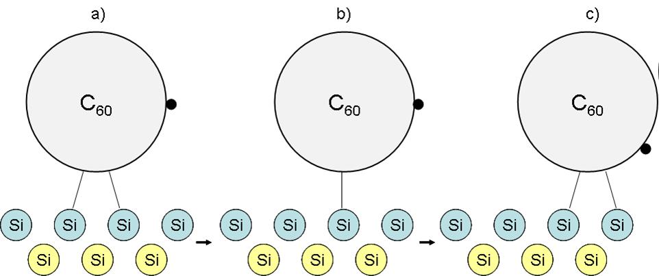
The results provided insights into the dynamical response of covalently bound molecules to manipulation. The sequential breaking and reforming of highly directional covalent bonds resulted in a dynamical molecular response in which bond breaking, rotation, and translation are intimately coupled in a rolling motion, but not performing sliding or hopping motion.
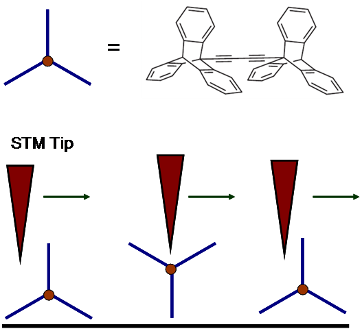
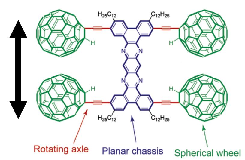
A triptycene wheeled dimeric molecule Figure \(\PageIndex{4}\) was also synthesized for studying rolling motion under STM. This "tripod-like" triptycene wheel ulike a ball like C60 molecule also demonstrated a rolling motion on the surface. The two triptycene units were connected via a dialkynyl axle, for both desired molecule orientation sitting on surface and directional preference of the rolling motion. STM controlling and imaging was demonstrated, including the mechanism Figure \(\PageIndex{4}\).
Single Molecule Nanocar Under STM Imaging
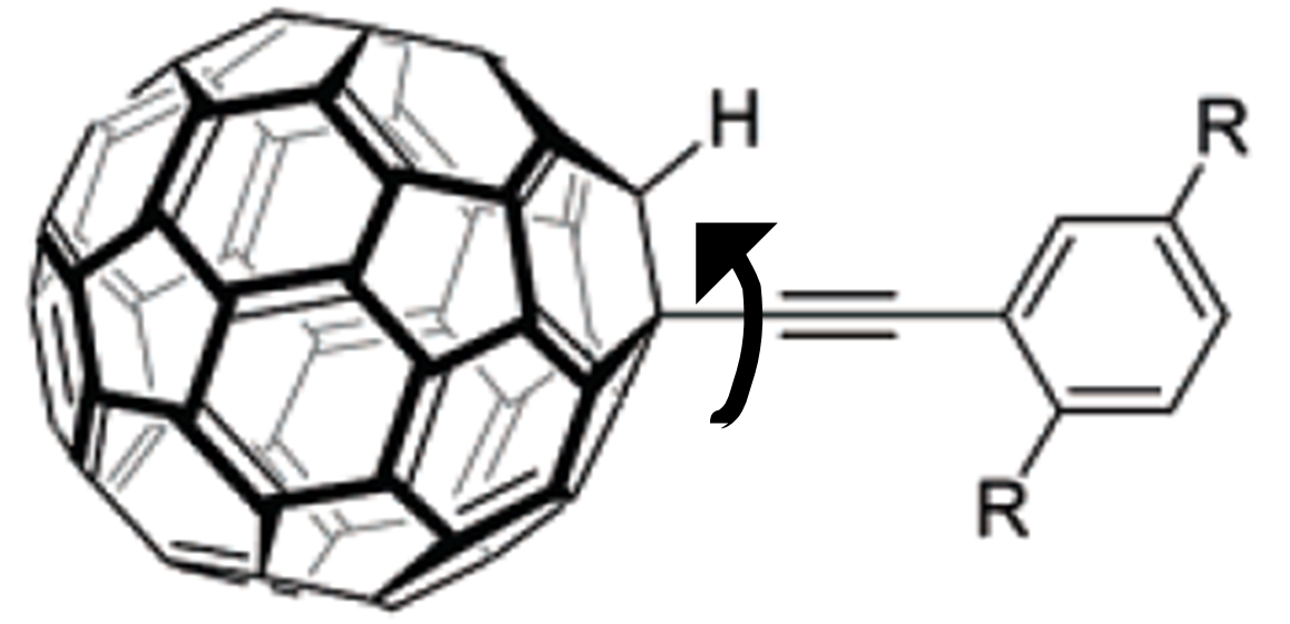
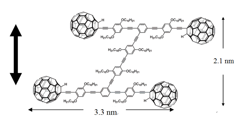
Another use of STM imaging at single molecule imaging is the single molecule nanocar by the Tour group at Rice University. The concept of a nanocar initially employed the free rotation of a C-C single bond between a spherical C60 molecule and an alkyne, Figure \(\PageIndex{5}\). Based on this concept, an “axle” can be designed into which are mounted C60 “wheels” connected with a “chassis” to construct the “nanocar”. Nanocars with this design are expected to have a directional movement perpendicular to the axle. Unfortunately, the first generation nanocar (named “nanotruck” Figure \(\PageIndex{6}\)) encountered some difficulties in STM imaging due to its chemical instability and insolubility. Therefore, a new of design of nanocar based on OPE has been synthesized Figure \(\PageIndex{7}\).
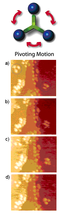
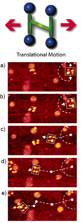
The newly designed nanocar was studied with STM. When the nanocar was heated to ~200 °C, noticeable displacements of the nanocar were observed under selected images from a 10 min STM experiment Figure \(\PageIndex{8}\). The phenomenon that the nanocar moved only at high temperature was attributed their stability to a relatively strong adhesion force between the fullerene wheels and the underlying gold. The series of images showed both pivotal and translational motions on the surfaces.
Although literature studies suggested that the C60 molecule rolls on the surface, in the nanocar movement studies it is still not possible to conclusively conclude that the nanocar moves on surface exclusively via a rolling mechanism. Hopping, sliding and other moving modes could also be responsible for the movement of the nanocar since the experiment was carried out at high temperature conditions, making the C60 molecules more energetic to overcome interactions between surfaces.
To tackle the question of the mode of translation, a trimeric “nano-tricycle” has been synthesized. If the movement of fullerene-wheeled nanocar was based on a hopping or sliding mechanism, the trimer should give observable translational motions like the four-wheeled nanocar, however, if rolling is the operable motion then the nano-tricycle should rotate on an axis, but not translate across the surface. The result of the imaging experiment of the trimer at ~200 °C (Figure \(\PageIndex{9}\)), yielded very small and insignificant translational displacements in comparison to 4-wheel nanocar (Figure \(\PageIndex{9}\)). The trimeric 3-wheel nanocar showed some pivoting motions in the images. This motion type can be attributed to the directional preferences of the wheels mounted on the trimer causing the car to rotate. All the experimental results suggested that a C60-based nanocar moves via a rolling motion rather than hopping and sliding. In addition, the fact that the thermally driven nanocar only moves in high temperature also suggests that four C60 have very strong interactions to the surface.