
Sample and Hold Settling Time
- Page ID
- 60143

Sample and Hold Circuit
"Time is what keeps everything from happening at once." If we want to measure a signal, we can not ignore the fact that it changes with time. There are several approaches to dealing with this. We could measure the signal very fast, do it many times, and after we're done figure out what the right time scale would have been. We could average the signal. Or we can snatch the value of the signal, hold that value steady, and digitize the single, sampled value at our leisure. A sample and hold circuit (or its first cousin, track and hold) can be employed with digitizers to pluck a single value from an analog source, keep that value stable for at least the time required for digitization, and can then be set to grab (sample) a value at a later time.
Consider the following circuit:
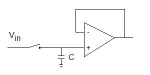
If the switch is closed, the capacitor is charged to the potential Vin. When the switch opens, the capacitor holds its charge, so the follower op amp has an output potential of what potential was on the capacitor at the moment the switch opened. If the switch is typically closed, but opens momentarily when we want to make a measurement, this is a track and hold circuit. If we typically leave the switch open, but momentarily close it when we want to grab a measurement, it is a sample and hold circuit.
This sounds too easy. Time for a reality check.
Settling Time for Sample and Hold
The potential which we sample comes from some source with non-zero internal resistance. We thus recognize that, when the switch is closed, we are looking at an RC circuit. The capacitance is obvious -- it's the C in the circuit. What about the R? The output resistance of typical operational amplifiers is between 1 Ω and 1000 Ω. If we always put a buffer amplifer before the switch, then the RC time constant for this circuit is between C seconds and 1000C seconds, with C in Farads. Review time!
Fill in the following table. What is the RC time constant for each combination of R and C?
| 1 pF | 1 nF | 1 μF | |
|---|---|---|---|
| 1 Ω | |||
| 10 Ω | |||
| 100 Ω | |||
| 1000 Ω |
From this, we see that the rate of response can vary over many orders of magnitude. The lower the capacitance, the less charge is needed to represent a given potential, but the greater the influence of shot noise on the measurement. 1 V stored on 1 pF is about 16 million electrons, which has an uncertainty of 1 part in 4000. Such a small capacitor is inappropriate for even a 12 bit converter, much less something with greater resolution. 1 V stored on 1 μF is about 1.6 × 10¹² electrons, with an uncertainty of 1 part in 4 × 10⁶, about the resolution of a 24 bit converter.
To think about: even without any knowledge of the inside workings of an analog-to-digital converter, why will high resolution conversions always be slower then low-resolution conversions?
Ignoring all nonidealities, recall that it takes longer than one RC time constant to accurately reach a steady state voltage on a capacitor. Let's do another exercise. Recall that Vcap = Vstep(1-exp-t/RC). So let's figure out how long it takes to get the accuracy of a sample and hold circuit to some number of bits. We already worked problems like this in the section on digital to analog conversion.
If RC = 1 μs, how long must the sampling switch for the sample and hold stay closed to get the capacitor charged adequately for 16 bit accuracy?
A track and hold does not see jumps in input as often as a sample and hold, so if there are long pauses between taking samples, a track and hold reaches high precision more quickly than a sample and hold. Because it is easy to signal average a long list of numbers, it has become common to take data very fast, then average or take subsets of the data for emulating infrequent measurements. Thus, sample and hold is more common than track and hold.
Unfortunately, there are non-idealities, so just dealing with RC time constants is over-optimistic. The switch does not turn on or turn off instantaneously. There is some resistance associated with the switch when it is on, and some stray capacitance when it is off. During switching, there are noise spikes or glitches. Thus, after the switch opens, one must wait some period (usually less than 1 μs) before starting digitization. Given the numbers in the last problem above, it is little wonder that typical 16 bit analog to digital conversion for many years was limited to 50 to 100 kHz. In recent years, conversion rates over 1 MHz have become common. What led to the change? Low resistance switches with few glitches, and the smallest possible capacitors.