
D. Potentiostats
- Page ID
- 61544

A potentiostat is a device that controls the potential applied to a working electrode (WE), relative to a reference electrode (RE), and measures the current flowing between the working electrode and a third electrode, called the auxiliary electrode (AE). These devices can be constructed using operational amplifiers (OAs), which are circuit components having dual inputs of very high impedance. One of the inputs inverts the polarity of the applied signal (the inverting input, -), while the other is noninverting (+) with respect to the input polarity.
Most practical applications of OAs use some form of signal feedback between the output and one of the inputs. The simplest such device is called a voltage follower, illustrated in Figure 37. OAs are represented in circuit diagrams as triangles.
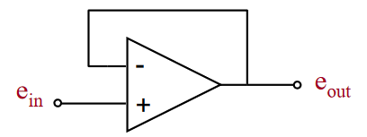
Figure 37
The voltage follower detects any imbalance between the two inputs signals, and works diligently to maintain a null difference between them by adjusting the output voltage to an appropriate value. For the voltage follower illustrated above, eout = ein. When used in the design of a potentiostat, the high input impedance of the voltage follower is used to isolate the reference electrode and prevent appreciable current from passing through it.
A basic potentiostat constructed from three OAs is shown in Figure 38, with connections illustrated to the three electrodes located in a typical electrochemical cell.
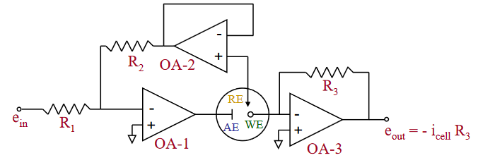
Figure 38
In simple terms, this circuit is designed to “sense” the potential difference between the working electrode (WE) and the reference electrode (RE). This difference is measured at the voltage follower OA-2. The applied potential of the WE is changed by increasing or decreasing the input voltage (ein) at the control amplifier OA-1. Since the output of OA-2 is the feedback signal to OA-1, a change in ein away from the fixed potential of the reference electrode (eref when R1 = R2) causes OA-1 to force current into the electrochemical cell between the auxiliary electrode (AE) and the WE to balance the difference in the inputs at OA-1. The current flowing in the cell as a function of the changing potential output of the control amplifier can be measured as a voltage drop across the feedback resistor in OA-3 (i = eout / R3). OA-3 is configured as a current follower, whose output is generally amplified before it is sent to a recording or display device. Potential during a scan can be monitored at the output of OA-2. This monitored potential is the negative of the actual WE potential, as the WE is held at virtual ground when the current follower is used.
The input voltage, ein, to the control amplifier can be supplied by an external potential source or waveform generator. Commonly used input signals include potential steps, and either triangle or staircase type waveforms that increase/decrease in a linear fashion.
In the arrangement shown above, no current is allowed to pass to the RE because of the high input impedance of OA-2. This allows the activities of the reference half-cell components, and thus the reference potential, to remain unchanged during the experiment.
More information on the fabrication and operation of potentiostats can be found in References 31-32.