
ii) Important parameters in CV
- Page ID
- 61490

Cyclic voltammograms are most often characterized by: a) the location of the forward and reverse peaks on the potential axis (Ep and ∆Ep, allowing the calculation of E0’); b) the ratio of currents observed on the reverse and forward scans (ip,rev / ip,fwd); and c) the dependence of peak currents on the scan rate (ip vs. ν1/2). As before, an uncomplicated, chemically and electrochemically reversible redox system will first be described. Next, deviations from the reversible case will be presented, and the resulting changes in the appearance of the voltammograms obtained will be used as diagnostic criteria for electrode reaction mechanisms of varying types.
Peak Location
In the forward scan of a cyclic voltammogram, the conditions that exist at the surface of the electrode are the same as those we have previously described for linear scan voltammetry. For conditions that include an electrode product that is stable on the time scale of the potential scan, the presence of a return peak in cyclic voltammetry allows us to now determine the formal potential for a redox couple, E0’, by averaging the two peak potentials
\[\mathrm{{E^0}' = \dfrac{E_{p,f} + E_{p,r}}{2}}\]
where Ep,f and Ep,r represent the forward and reverse peak potentials, respectively. The position of the E0’ is characteristic of a redox species in much the same way that the wavelength of maximum absorbance is characteristic of a species in spectroscopic experiments.
The separation between the two peak potentials, ∆Ep can be used determine the electrochemical reversibility for a redox couple, with
\[\mathrm{∆E_p = \dfrac{0.058}{n}}\]
for the reversible case (∆Ep in volts). This value is independent of the scan rate for fast electron transfer. Increasing values of ∆Ep as a function of increasing scan rate indicates the presence of electrochemical irreversibility. The value of ∆Ep can be used in the calculation of the heterogenous electron transfer rate constant (ks) for the redox reaction.
In practice, the theoretical value of (58/n) mV for ∆Ep is seldom observed. A known reversible standard compound (like ferrocene or ferricyanide) is often helpful in the measurement of practical values for ∆Ep under the specific experimental conditions being used in the characterization of an unknown compound. The ∆Ep is also useful in the determination of n-values, as a two-electron transfer (n = 2) will give about 29 mV for the reversible case.
Current Ratios
In cyclic voltammetry, we are given the opportunity to directly observe the stability of the electrochemically generated product. If the product is stable on the time scale of the experiment, the peak current observed for the return potential scan (ip,r) should be equal to that seen for the forward potential scan (ip,f) given reversible electron transfer reactions in both directions.
\[\mathrm{\dfrac{i_{p,r}}{i_{p,f}} = 1.0}\]
The measurement of peak current is sometimes complicated by the difficulty in locating a proper “baseline” from which to define the magnitude of a peak. If no other peaks are present, the baseline for the forward wave can generally be defined by extrapolating the zero current portion of the scan to a position under the forward peak. The reverse peak current is more often problematic, with baselines affected by the location of the switching potential, among other things. Proper extrapolation of baselines for peak current measurement in the absence of complications is shown at left in the Figure 19. Many computer-controlled potentiostats have data systems that can accurately and quickly make these types of measurements. For situations where baseline assignment is more complicated, the current ratio can sometimes be conveniently calculated using the empirical method of Nicholson7, which requires the measurement of the forward (ip,f) and reverse peak currents (designated (ip,r)0 to differentiate it from that used previously) from the same baseline, along with a third current, iλ, which is the current measured at the switching potential. This method is illustrated at right in Figure 19. (DigiElch simulation conditions same as in Figure 18.)
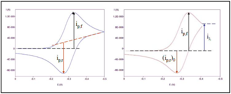
Figure 19
The currents measured using the method of Nicholson can then be applied to the calculation of (ip,r / ip,f) by
\[\mathrm{\dfrac{i_{p,r}}{i_{p,f}} = \dfrac{(i_{p,r})_0}{i_{p,f}} + 0.48 \dfrac{i_λ}{i_{p,f}} + 0.086}\]
Scan Rate Dependence of Peak Current
We learned in our discussion of LSV that the observed peak current on the forward potential scan is given for the case of reversible electron transfer by the Randles-Sevcik equation (at 25 oC)
\[\mathrm{i_p = (2.69 \times 10^5)\, n^{3/2}\, A\, D^{1/2}\,C_i\,}v^{1/2}\]
Thus, peak currents will increase linearly as a function of the square root of the scan rate for reversible electron transfer. Plots of ip vs. ν1/2 are useful in the characterization of electrochemically reversible redox systems. Deviations from linearity are indicative either of complications in the kinetics of the observed electron transfer, or the result of chemical changes which occur as a result of the electron transfer (homogeneous reactions).
A similar indicator of reversible electron transfer is called the current function, whose value is given by (ip / ν1/2). The current function should be constant for all scan rates for which the electron transfer is fast enough to maintain the equilibrium ratio between the reduced and the oxidized forms of the redox couple predicted by the Nernst equation.
At this point, it is instructive to note that when describing electrochemical reversibility it is important to consider not only the value of ks, the heterogeneous electron transfer rate constant, but the scan rate as well. It should be clear that even for large values of ks there exists some values of scan rate for which Nernstian equilibrium cannot be maintained at the electrode surface. At these scan rates, the observed voltammetry will display characteristics of quasi-reversible or irreversible behavior, such as the drawing out of voltammetric peaks over wider potential ranges, decreased peak currents, and increased values for ∆Ep.